The CMU Rover Fully Independent Drive
At the time of this writing [1983] Dr. Hans Moravec at Carnegie-Mellon University is constructing a new mobile robotic testbed.
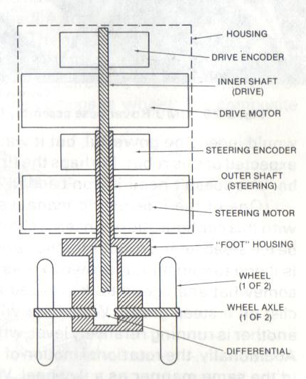
This configuration has a similar base arrangement to the synchro drive system, except that each foot is totally independent for both steering and power. The "feet" also have a wheel on each side, powered through a differential. This arrangement greatly improves the flexibility of the carriage system. Each "foot" assembly contains an encoder for both steering and power, allowing the drive computer to precisely control it. Early results indicate that the differential must have limited slip.
The CMU Rover System has joyous degrees of freedom for a wheeled system. It can turn in a mode like the synchro drive, or it can steer its wheels tangentially to the base and spin in circles. The lack of mechanical linkages should provide excellent efficiency, and maintenance should be relatively good. Control is of course more complex, but the CMU machine is being fitted with special low-power-consumption computers utilizing the extremely powerful MC68000, 16-bit microprocessor.
Since the Rover does not have a configurable base of support, its stability is limited. The combination of these wheels with such a base would indeed be powerful, but it was not required for the functions expected of this robot. Perhaps the first law of robotics design should be "If it doesn't need it, don't add it!"
One of the interesting maneuvers that Moravec is exploring"' with this configuration concerns climbing slopes that would normally be too steep for the robot's traction and power (not stability). The robot is made to spin about its own axis as it approaches the ramp. This is somewhat analogous to the zig-zag maneuver performed by a bicyclist on a steep grade. When one wheel is attacking the full grade, another is running relatively level, while the third is moving downhill.
Additionally, the rotational motion of the robot serves to store energy in the same manner as a flywheel. While it seems unlikely that one would want to have factory robots pirouetting wildly about the floor, a subdued version of the maneuver might prove very useful.
This system is in keeping with the general trend away from mechanical complexity in electromechanical devices such as printers and manipulators. The electronic controls associated with these devices are being used to eliminate most of the mechanical intricacies, thus reducing cost and maintenance.
• Efficiency: Excellent
• Simplicity of Control: Fair (due to exceptional flexibility)
• Traction: Good
• Maneuverability: Excellent
• Navigation: Excellent
• Stability: Fair
• Adaptability: Dynamic adaptability only
• Destructiveness: Excellent
• Climbing: Poor
• Maintenance: Good
Hans P. Moravec
The Robotics Institute Carnegie-Mellon University
Pittsburgh, PA 15213 February 1984
This work has been supported at the Carnegie-Mellon University Robotics Institute since 1981 by the Office of Naval Research under contract number N00014-81-K-0503.
@heading(Abstract)
Our group has spent three years designing, building and struggling to make operational an ambitious mobile robot. The project was initiated with mixed objectives. The major purpose was to provide a vehicle for continued work in navigational vision begun at Stanford. A secondary goal was to build a high performance mobile platform able to act in concert with a future attached robot arm. The decision to pursue both efforts in a single robot, effectively holding the primary goal hostage to success of the secondary one, was a strategic error. Achieving the agility desired for a mobile extension of an arm was a much more interesting problem than we had guessed.
We've been working on the vision side of the work during the ordeal with stored images and simulations, and have recently completed a second, much simpler, vehicle to return that effort to the real world.
This paper tells the saga of the secondary goal; why it was undertaken, the problems it encountered, what we have learned from it, and how we are proceeding. The most interesting aspect is the need to control a highly overconstrained system, a problem occurring (and often ignored) in other areas of robotics, but presented with unique forcefulness by our wheelbase design. As we discovered in other aspects of mobile robot research, despite surface similarities there are remarkable differences between the problems imposed by mobile platforms and those of robot arms, and solutions for manipulation are rarely directly suitable for locomotion.
@heading(Introduction)
The Stanford Cart was a television equipped but otherwise very simple mobile robot controlled remotely by a sophisticated computer. From 1973 through 1979, as part of my PhD research, I wrote a program that could drive the Cart through cluttered obstacle courses using the onboard camera to locate and track objects, and, significantly, to visually servo the robot's movements with high accuracy despite terrible sloppiness in its mechanics. The problem was harder than I had guessed in my early musings, and the final program took no less than five hours to drive the robot over 20 meter routes @cite(Moravec80).
The surprising difficulty of the problem, among other circumstantial evidence, convinced me that working with autonomous mobility confronts one with the key problems of perception and the foundations of intelligence in a uniquely effective way @cite(Moravec83). This insight greatly encouraged the work, and led me to take extra risks.
The optimism was inflated at CMU when, in 1981, we received an Office of Naval Research contract sufficiently large to develop a very elaborate roving robot system.
Early ideas for the vehicle were pedestrian; a conventionally steered three wheeled platform carrying a camera system similar to the Cart's, but with onboard processing for more precise motor servoing and simple sensing. The prospect of a plodding continuation of the Cart work left me dissatisfied and I sought to spice the challenge.
Hari Asada, now of MIT, then my office neighbor, shared his concept of robot mobility. Hari, with Takeo Kanade, had been studying direct drive robot arms, where high torque, gearless electric motors, with low friction and precise torque characteristics promised manipulator speed and precision not possible in conventional designs. Hari's vision was of a mobile robot at the base of a robot arm acting with the arm in manipulation tasks. The mobile base would be like a shoulder joint with enormous reach, high strength, moderate speed and modest accuracy. Limitless applications came
to mind. He convinced me.
@heading(Conception)
The first major decision was what the wheelbase should be like to best support the manipulation task. Conventional drive designs allow instantaneous motion with only two degrees of freedom (DOF); usually forward speed and radius of steering curvature; sideways motion is not possible.
The usefulness to a manipulator would be enhanced if the base could move with a full three degrees of freedom (dubbed omnidirectional motion). Any vehicle with a fixed conventional wheel is constrained to two DOF, therefore an omnidirectional vehicle can have no fixed conventional wheels. Spherical wheels came to mind immediately, but at the time I saw no way of controlling a spherical wheel in two or three DOF without high frictional losses (a solution has since cropped up, but it is more complicated than competing omnidirectional techniques). Most straightforward seemed to be to make all wheels of the vehicle steerable. A round chassis with three steerable assemblies seemed simplest and most general. The robot, with batteries, motors, mechanical structure, cameras and other electronics would weigh at least 100 Kg. If each wheel was placed directly under its steering axis, steering while the robot was not moving would be difficult or impossible because of high friction with the floor. Putting the wheels off-center would alleviate this problem, but the robot would be less stable. I opted for what seemed like a clever idea; a pair of off-center wheels connected by a differential gear. This basic idea, the need to make everything compact, power efficient and self contained, and the willingness to risk new techniques at any stage (this was basic research, after all), led to the following design. The first CMU Rover, now named Pluto, was built according to this plan and was substantially finished by 1983.
@heading(The Early Design)
This section describes only Pluto's hardware as it actually existed at the end of 1983. For other aspects of the grand plan see @cite(Moravec83).
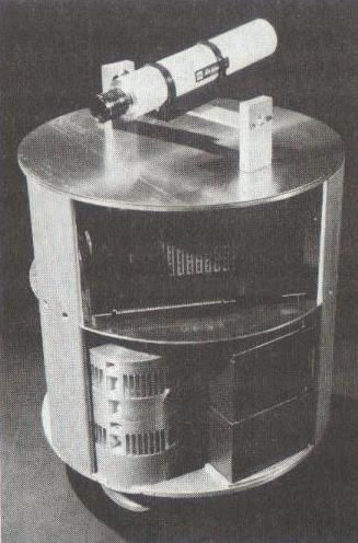
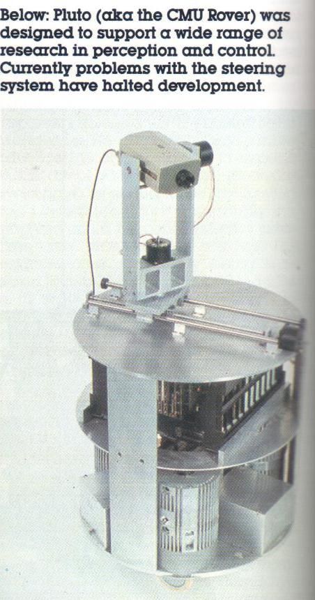
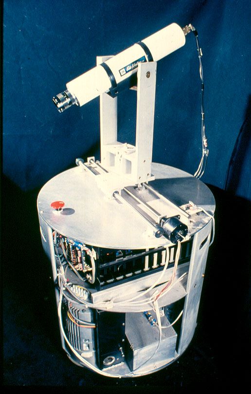
The robot is cylindrical, about a meter tall and 55 cm in diameter (Figure 1) and has three individually steerable wheel assemblies which give it a full three degrees of freedom of mobility in the plane (Figure 2). It carries a TV camera on a pan/tilt/slide mount. It contains eight onboard processors for servo control and communication and is linked by serial line to an outboard 68000 and a Vax.
Omnidirectional mobility is achieved by mounting the chassis on three independently steerable wheel assemblies. The control algorithm for this arrangement at every instant orients the wheels so that lines through their axles meet at a common point. Properly orchestrated this design would permit motion in any direction, and control of the robot's rotation about its own vertical axis. An unexpected benefit of this agility is the availability of a "reducing gear" effect. By turning about the vertical axis while moving forward the robot derives a mechanical advantage for its motors. For a given motor speed, the faster the Rover spins, the slower it travels forward, and the steeper the slope it can climb.
To permit low friction steering while the robot is stationary, each assembly has two parallel wheels connected by a differential gear. The drive shaft of the differential goes straight up into the body of the robot. A concentric hollow shaft around this one connects to the housing of the differential (Figure 3). Turning the inner shaft causes the wheels to roll forwards or backwards, turning the outer one steers the assembly, with the two wheels rolling in a little circle.
Each shaft is connected to a motor and a 4000 count/revolution optical shaft encoder. The two motors and two encoders are stacked pancake fashion on the wheel assembly, speared by the shafts. There are no gears except for the ones in the differential.
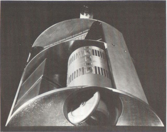
The motors are brushless with samarium-cobalt permanent magnet rotors and three-phase windings. With the high energy magnet material, this design has better performance when the coils are properly sequenced than a conventional rotating coil motor. The coils for each are energized by six power MOSFETs mounted in the motor casing and switched by six opto-isolators (to protect the controlling computers from switching noise) whose LEDs are connected in bidirectional pairs in a delta configuration, and lit by three logic signals connected to the vertices of the delta (Figure 4).
The motor sequencing signals come directly from onboard microprocessors, one for each motor. These are CMOS 6805s to keep power consumption low. Each processor pulse width modulates and phases its motor's windings, and observes its shaft encoder to servo the motor to a desired motion. The 6805s get their marching orders over a shared serial line from an onboard 68000 that communicates with an outboard 68000 that runs the co-ordinating program. One other 6805 controls three stepping motors to pan, tilt and slide the camera assembly.
The Rover is powered by six sealed lead-acid batteries. The motors are powered directly from these, the rest of the circuitry derives its power indirectly from them through switching DC/DC converters.
@heading(Experiments and Experiences)
Experiments with Pluto during and after construction revealed some severe problems. Many of them required repeated disassembly and assembly of the motor stacks. The nested and stacked design made this a very arduous and time consuming process.
@begin(itemize)
@i(Malfunctions of the wheel assembly shaft encoders, including breakages of the glass encoder disks.) The differential wheel assemblies had an unexpected amount of motor shaft runout when weight was removed from the wheels. The modular encoder disks are attached to the shafts, while the optical sensor and electronics are attached to the shaft, with a required clearance of only 0.05 mm, on the wrong side. We solved the problem by replacing the encoders with a type that can be mounted upside down to accommodate the runout without damage. We still noticed occasional loss of calibration and damage in some of the encoders. We built sturdier encoder mountings, and assembled the stacks more carefully. The encoders seem to be holding for now, but are still a source of worry. We are considering a new design with different, pre-assembled, encoders and flexible couplings should any fail again.
@i(Loss of traction of the differential wheels on slight floor irregularities.) Each of the three wheel assemblies had two wheels connected by a differential gear. Three points define a plane, and the rover often encountered situations where most of its weight was borne by one wheel of each differential, resulting in loss of traction because of the nature of the differentials. We tried different tire materials, but failed to solve the problem this way. We did succeed by a radical alteration; removal of one wheel from each assembly and locking of the differential gear. By slightly reducing the wheel diameter we were also able to decouple drive motor from steering torque, improving the servo characteristics.
@i(Burnout of the motor driver field-effect transistors.) For compactness, power efficiency and in hopes of giving the mobile base the precision and controllability to provide three degrees of freedom of motion for a future attached manipulator, I chose a direct drive design using samarium-cobalt brushless motors. To contain motor switching noise, the driver circuitry is in the motor case optically coupled to the outside and uses power FETs for their high current gain. The FETs were new and the largest available when I chose them in 1981, and their specifications (12 amps, 60 volts) seemed adequate for the motors (10 amps, 24 volts). Initial testing turned up no problems. Sustained runs of the completed rover proved otherwise. We destroyed about one transistor for every half hour of operation of the six motors. We did extensive bench testing, but found it difficult to re-create the problem; all our measurements were within spec, and our transistors survived. Recent data from the manufacturer told us the problem. The ratings in the old specs are at 25 degrees C; at 100 degrees the ratings drop by a factor of three. Our drivers approach the higher temperature only after sustained runs at high loads. Fortunately FET technology was marching on. The largest FETs available now have three times the capacity of the 1981 variety. We installed the new ones, and have had no problems since.
@i(Severe oscillations and other errors in servoing the drive and steering motors.) We put much effort into simulations of the wheel motors in order to develop servo code for the motor processors before fabrication of the motors was complete. Most of this early effort went for naught because the simulations inadequately modeled backlash and other non-linearities and also because the motor processors were too slow to implement the algorithms with sufficient time resolution. We re-iterated much of the development in a bench setup with an actual motor and processor, and developed code that seemed able to servo position and velocity @cite(Muir84). We found the robot could be driven reasonably well with this code if only one wheel assembly was energized (the other two steering-locked and freewheeling). With all three running the robot mostly shook and made grinding noises. Something strange was going on. We tried simplifying the loops, with a position servo on steering and a velocity servo on the drive motors. The robot now moves, but unsteadily and with oscillation. The persistent problems triggered an insight; we had an unexpectedly interesting problem.
@end(itemize)
@heading(Too Much Control)
I had chosen the original control configuration, a processor for each motor all orchestrated by another processor, partly in imitation of the successful controller for Unimation's PUMA manipulator. The apparent correctness of this choice was amplified by a co-incidence.
In 1981 after the basic design for Pluto had been specified, I learned of a Unimation funded Stanford mechanical engineering project building an omnidirectional robot nearly the same size and shape as ours @cite(Carlisle81). The machine achieved omnidirectionality in a different manner; three motors driving three symmetrically placed wheels of strange design. Each wheel had rollers in place of tires that allowed the wheel to be passively rolled sideways as well as driving backward and forward under motor control @cite(La81). The robot used a slightly modified PUMA controller to drive its wheels. By 1983 the Stanford/Unimation design was built and its controllability verified.
Our experiences indicated emphatically that there was a fundamental difference between our design and the Stanford one. The problem was in the interaction of the six servo loops. In the Stanford/Unimation design, where three motors control three degrees of freedom, the interaction is small and can be ignored with only moderate loss of performance; similar considerations apply to manipulators.
Pluto's drive system, on the other hand, with six motors, is overdetermined (or overconstrained). In addition to moving the robot forward, sideways and spinning it about its axis, the individually drivable and steerable wheels are able to attempt to twist, compress and stretch the floor in various interesting ways. Our naive control method excites these modes, and the robot shakes and rattles in a way we cannot ignore.
Similar problems have been encountered in the context of walking machines @cite(Orin81) and manipulators doing pushing operations like inserting a peg in a hole with tight tolerances @cite(Mason82). The Ohio State University walking machine group has suggested two solutions. One involves solving a large linear programming problem in the servo loop to minimize a total energy function. It requires a presently unavailable amount of real-time computer power. Their other solution is easy to implement, and involves putting a torque term in each feedback loop error expression. This effectively puts a damped spring in each axis, limiting the forces that redundant actuators will exert on each other in case of small disagreements. The price paid for this is a softness in the control, for instance a sag when climbing a slope. Neither approach entirely solves Pluto's problems.
@heading(An Approach)
Controlling Pluto's overconstrained wheelbase has thus become an interesting research problem in its own right, one we have just begun to investigate. Its now seems to us that six independent servo loops on six motors is a fundamentally wrong way to control three degrees of motion. It is necessary in some way to eliminate the conditions that permit pairs of motors to engage in tugs of war while trying to drive the robot.
One idea we will be investigating is a system that mathematically combines the six direct motor motions to produce abstracted variables, three representing desirable modes of operation, and the other three being undesirable floor stretching modes. Servo loops will control these derived variables, trying to zero the undesirable modes and to drive the robot with the others. The error signals generated by these loops will be transformed by a mathematical operation inverse to the one by which their variables were derived, producing drive signals for the motors. The desirable modes might be the X, Y and angular velocity of the robot as a whole, or alternatively the direction, speed and radius of curvature of its trajectory. Undesirable modes would involve discrepancies in steering angle and in drive speed of the different wheel assemblies.
One of the most serious bad modes is a castering effect that happens when one of the wheels falls behind the motion of the robot as a whole. The assemblies now have only one wheel each since we did away with the differential, and this wheel is placed to the side of the steering axis. Once the wheel falls back a little, robot motion produces a force that drives the steering even further off the correct heading. This mode can be countered both by torquing the steering motor for the wheel and by accelerating the drive motor. This mode will have to be stiffly servoed since it gets worse if left alone. Other undesirable modes, such a differing toruqes on different drive wheels would need less stiff servoing since they passively correct themselves.
@heading(Conclusion)
We built Pluto primarily to continue our work in computer vision, but decided to incorporate interesting new capabilities, and to utilize interesting new techniques. The interest level rose higher than we had bargained for, and we spent three years battling severe interlocked problems. As the dust settles we are left with an interesting and important control problem that we look forward to systematically solving. Until it is solved, Pluto will be unsuitable for vision work.
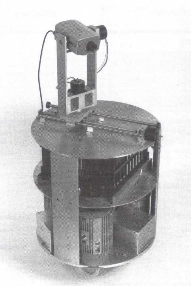
In the meantime we have built a very simple mobile robot for the vision work. Neptune uses synchronous motors driven off line frequency to sidestep the servo issue completely, and was fully operational three months after we started work on it. It has already visually servoed its motion and avoided many obstacles.
I suppose this might be called the divide and conquer problem solving strategy.
@heading(Acknowledgment)
In the last year Pat Muir has uncomplainingly suffered through Pluto's woes, valiantly trying to write a control thesis on a machine that blew transistors and mangled shaft encoders every few days and that required weeks of his labor to disassemble, assemble and recalibrate to repair those problems. The new control insight is due entirely to Pat's efforts. Gregg Podnar completed the Pluto's electrical system, and took care of the many of the redesigns and retrofits this sickly machine required. Gregg also designed and built Neptune's body in record time. Karen Hensley designed all the major mechanical components of Pluto, as well as the door opening arm we didn't even mention in this paper. Mike Blackwell has done all our microprocessor designs, except for the earliest ones which were done by Andy Gruss. Neptune carries one processor for motor timing, Pluto has eight, the better to shake with. Kevin Dowling built Neptune's electrical system and the camera moving circuitry for Pluto. Larry Matthies and Chuck Thorpe developed and improved the visual obstacle avoiding code that now runs Neptune. Alberto Elfes wrote a high level control program for the robots that we don't use yet, as well as a Sonar mapping program that will be used soon. Richard Wallace joined us recently and has been fooling around with path planning and manipulation graphics.
This work has been supported at the Carnegie-Mellon University Robotics Institute since 1981 by the Office of Naval Research under contract number N00014-81-K-0503.
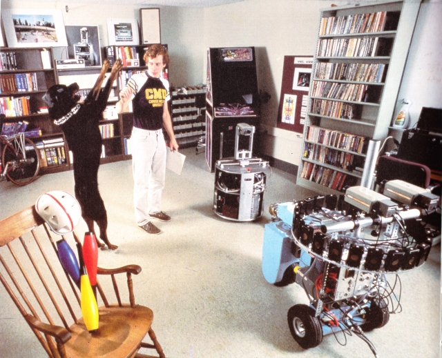
Pluto with its younger, more sophisticated brother – Neptune.