The Walking Gyro was conceived and built by John Jameson in 1981.
Article Source: Robotics Age, January 1985.
THE WALKING GYRO
John W Jameson
275 E. O'Keefe #7
Palo Alto, CA 94303
Walking machines generally fall into one of two categories: statically balanced or dynamically balanced. A statically balanced machine maintains stability at every position in its stride by always keeping its center of gravity aboye the region of contact between the machine and the surface.
A dynamically balanced machine is generally not statically stable at every stride position and must rely on intermittently applied control forces in order to keep upright. The Walking Gyro seems to fit best into the latter category, but its simplicity relative to other forms of dynamically stabilized walking machines makes it an attractive alternative for home experimentation.
Two characteristics are readily observed by experimentation with any toy gyroscope. One is the gyroscope's inherent stability, as illustrated by its ability to stay upright while keeping only one point in contact with a supporting surface. Another is the counter-intuitive reaction the device exhibits when the gyroscope is twisted about an axis perpendicular to the flywheel spin axis. The Walking Gyro utilizes both characteristics plus a third, gyroscopic precession, to provide a walking mobility base.
Although I have not yet constructed a model of the scale desirable for an experimental home robot, my analysis of the Walking Gyro's dynamics indicates that such a device is feasible. In fact, the analysis indicates that the stability and load-carrying capabilities increase dramatically with scale. Although the principies of the Walking Gyro are somewhat complicated, the basic mechanism is quite simple. Adding velocity and direction control offers a challenging (though not necessarily complicated) task for the home experimenter.
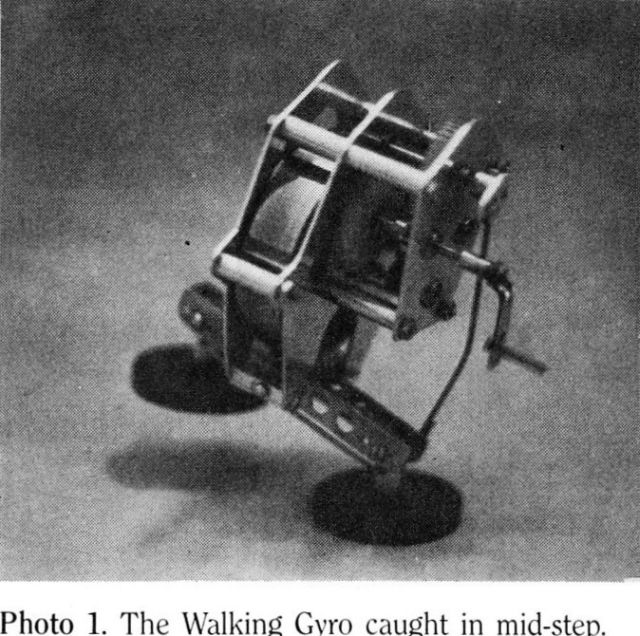
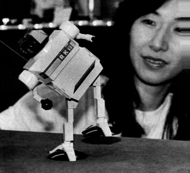
The Walking Gyro utilizes the angular momentum of a spinning flywheel to perform the following functions: lift the feet, balance during the stride via gyroscopic reaction torque, and move forward via gyroscopic precession. My prototype, shown in Photo 1, is powered by a hand crank and relies on energy stored in the flywheel to sustain motion.
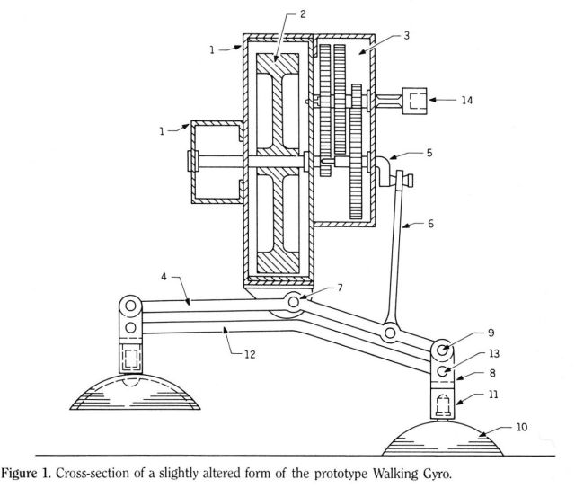
Figure 1 shows a side view, partially sectioned, of a Walking Gyro in mid-stride. The housing (1), which contains the flywheel (2), and the gear train (3), is caused to tilt back and forth with respect to the leg frame (4) by the crank (5) and link (6).
This motion is about the fore-and-aft pivot (7). The legs (8) are attached to the leg frame by the fore-and-aft pivots (9) and the feet (10) are attached to the legs by the vertical pivots (11). Finally, the horizontal bar (12) connects to both legs by the fore-and-aft pivots (13) so that they stay parallel. Note that in this particular presentation, the mechanism is equipped with an adaptor for a crank (14), which is used to bring the flywheel up to operating speed.
SIMPLE EXPLANATION
Caption Photo 1. The Walking Gyro caught in mid-step.
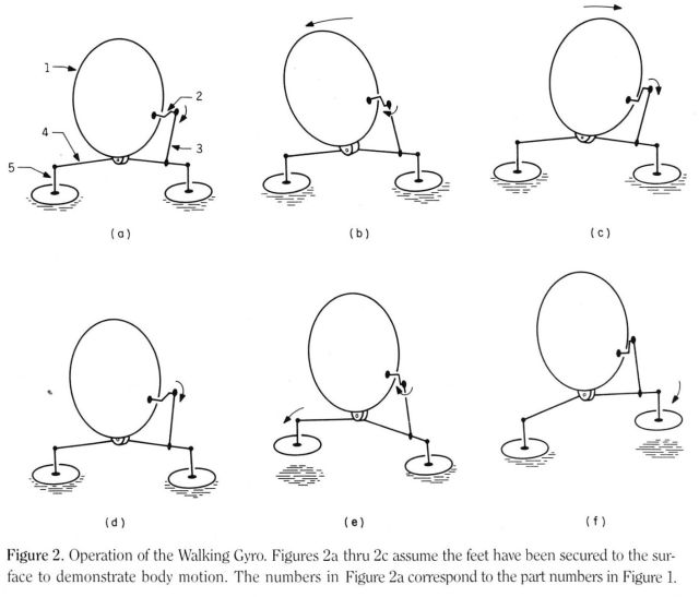
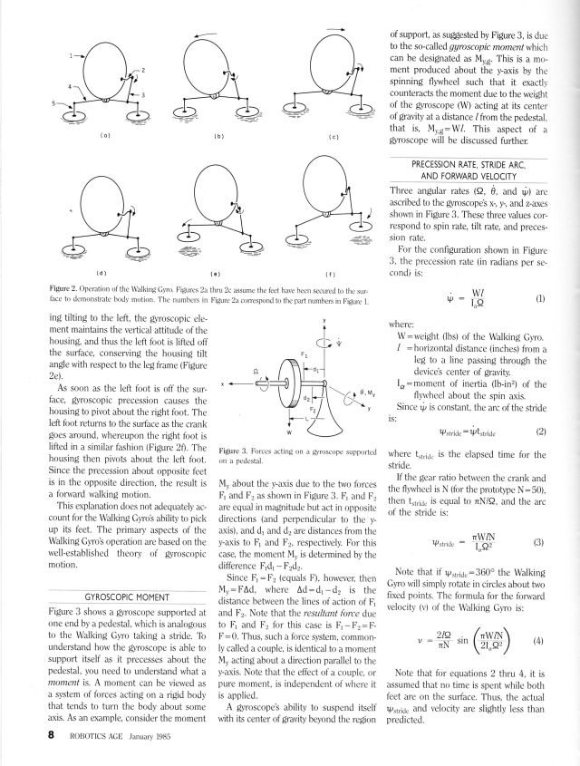
Figure 2 details the mechanism's movements. Figure 2a shows the Walking Gyroscope in a neutral position. Figures 2b and 2c show the motion that would occur if the feet were somehow attached to the walking surface. Figure 2b shows the housing tilting to the left, and Figure 2c shows a tilt to the right. Figures 2e and 2f show what happens if the same conditions of Figures 2b and 2c occur but with the feet free to move. Instead of the housing tilting to the left, the gyroscopic element maintains the vertical attitude of the housing, and thus the left foot is lifted off the surface, conserving the housing tilt angle with respect to the leg frame (Figure 2e).
As soon as the left foot is off the surface, gyroscopic precession causes the housing to pivot about the right foot. The left foot returns to the surface as the crank goes around, whereupon the right foot is lifted in a similar fashion (Figure 20. The housing then pivots about the left foot.
Since the precession about opposite feet is in the opposite direction, the result is a forward walking motion.
This explanation does not adequately account for the Walking Gyro's ability to pick up its feet. The primary aspects of the Walking Gyro's operation are based on the well-established theory of gyroscopic motion.
Figure 1. Cross-section of a slightly altered form of the prototype Walking Gyro.
See images for rest of article.
See full patent details here.
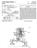
Patent number: 4365437
Filing date: Apr 15, 1981
Issue date: Dec 28, 1982
Toys based on Jameson's patent.
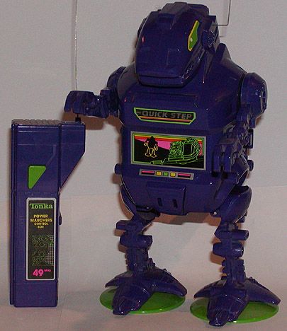
Remote-control to move robot in different directions.
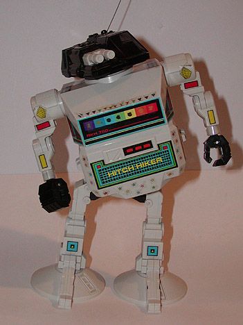
"Hitch Hiker" Walking Robot.
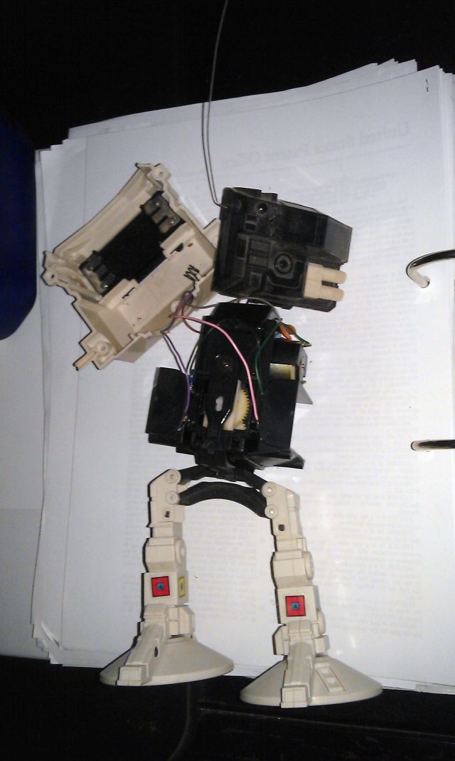
Showing the insides of the "Hitch Hiker" version.

Meccano model of The Walking Gyro.
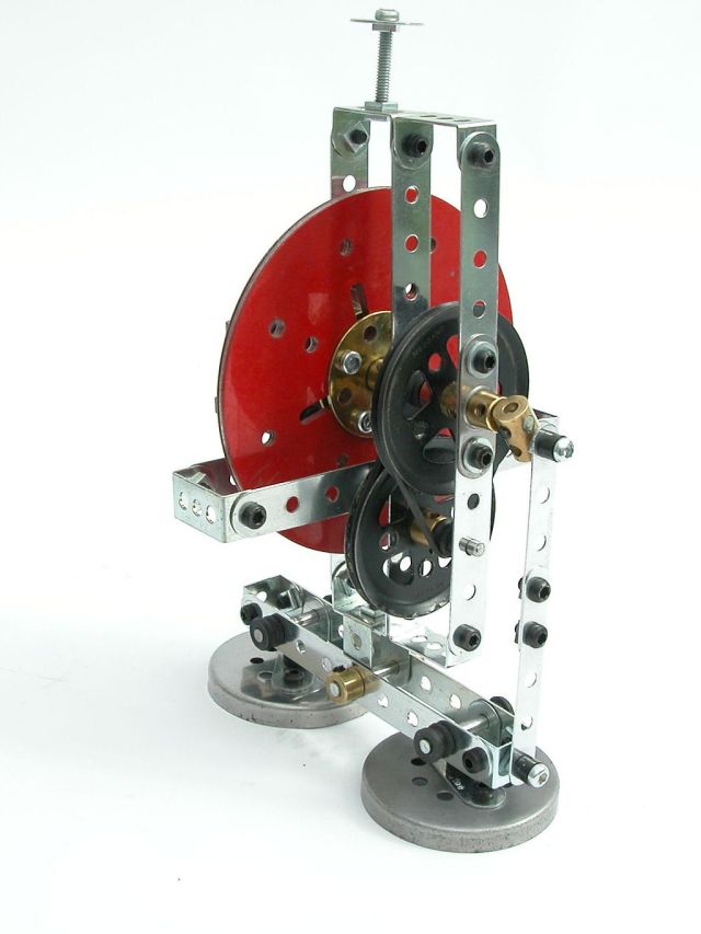
The Meccano model on the right was built by Bernard Perier from a Meccano set. Gyroscopic reaction force causes lifting of the feet and gyroscopic precession drives the motion forward.
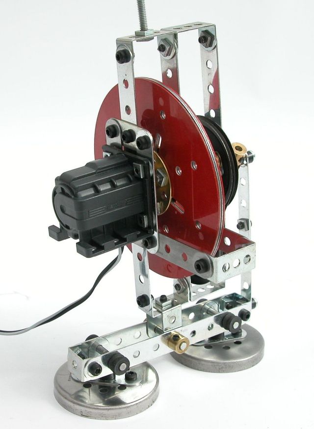
(photo by Stefan Tokarski)
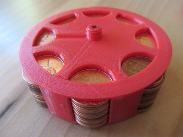
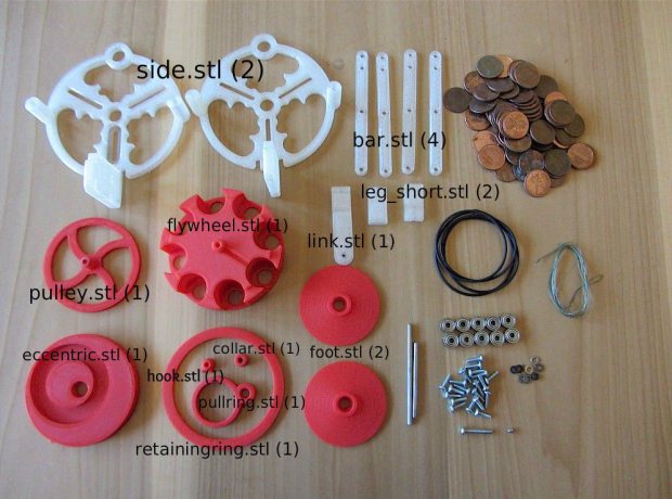
Gyroman 3D-printed by by Jeff Kerr from Make Magazine.
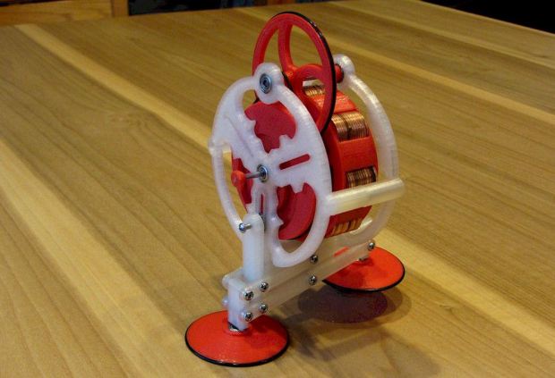
It would be great to see a scaled-up one of these at Burning Man with the driver as the payload.
**Update July 2015 – There’s a rumor that the original designer, John Jameson, is considering a giant, rideable version of Gyroman.
See also the Gyrocycle.
8 Replies to “1981 – The Walking Gyro – John W. Jameson (American)”
Comments are closed.