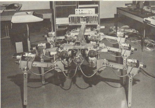
Earlier 1976 version sans stereo cameras.
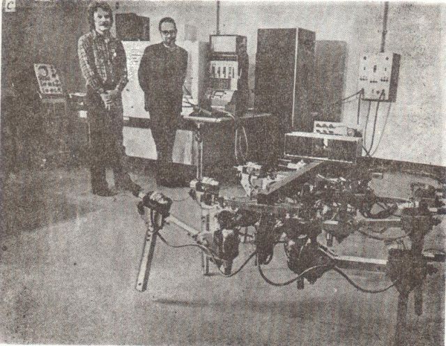
See a few seconds of McGhee's OSU Hexapod in motion in my walking machine compilation video clip.
Stop Press! 20 Oct 2010: Just found fabulous footage of this walker plus others. 50meg download. mp4 runs for 16 mins. see here.
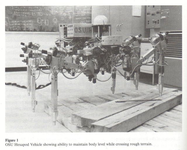
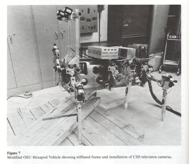
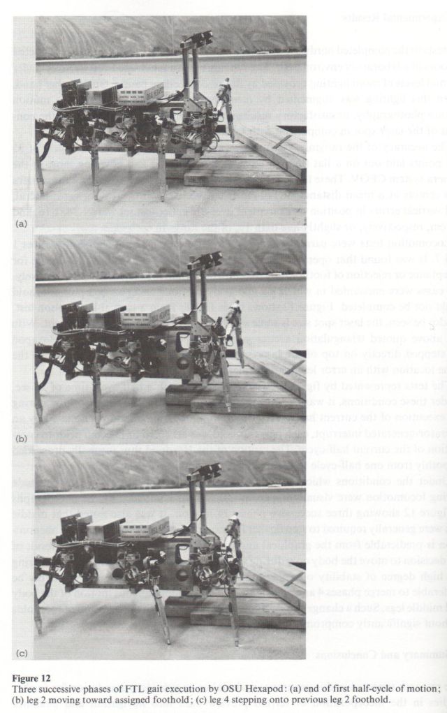
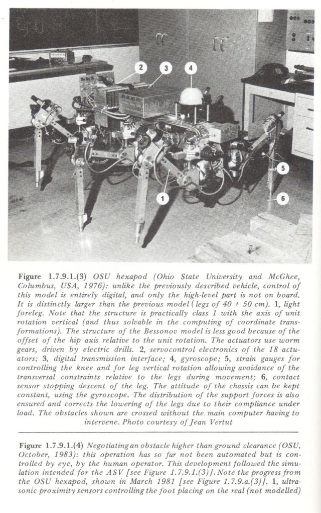
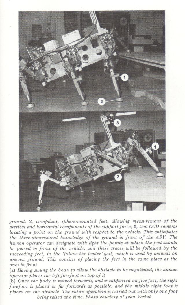
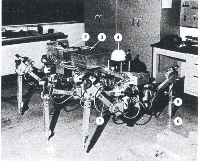
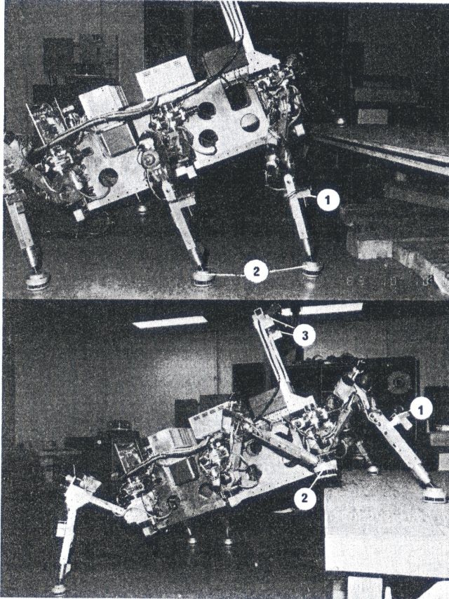
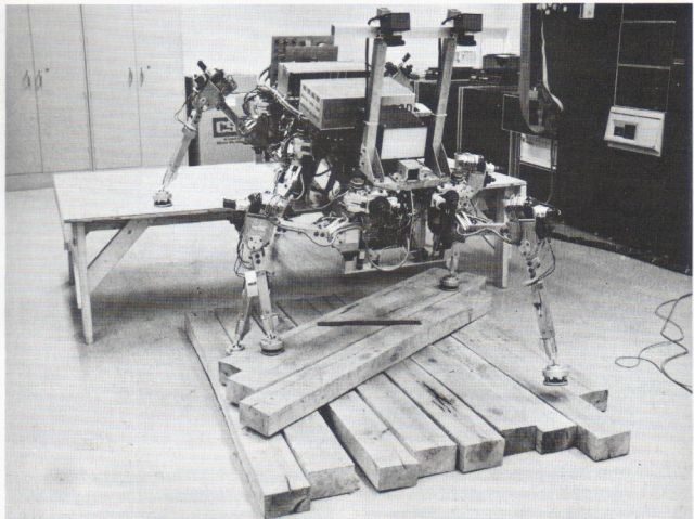
McGhee used Electric drill's to power the legs, similar to his earlier 'Phoney Pony'.
From Basic Robotic Concepts by John M. Holland, 1983.
The OSU Hexapod
At Ohio State University, Robert McGhee and his associates have spent a great deal of effort in perfecting a six-legged insectlike drive system called the "Hexapod" . This system is not the first of its kind to be constructed. That distinction probably belongs to the General Electric "Quadruped Transporter," which was a manually operated four-legged walker developed in the late 1960s. In fact, McGhee himself developed a four-legged walker at the University of Southern California in 1967 [RH- see 'Phoney Pony' link above]. The OSU Hexapod is, however, far more sophisticated in its control than any of these earlier projects. At this time its only rival exists in the Soviet Union, but a similar machine is under construction in Japan.
The Hexapod is being used to develop and test control hardware and software. The system is not intended to be independent, and so it is driven by ac line power through the use of triac controls. The Hexapod is kept tethered and is made to walk short distances over obstacles. One of the forelegs is instrumented with a set of strain gauges and is used for the more complex functions. This is in keeping with the very well proven research axiom of simplifying the problem to the basics.
As with most basic research, the most promising thing about the Hexapod is not the device itself, but the new concepts that are being generated and/or verified during its development. One of the most fundamental concepts that has been studied is "active compliance." This concept arises because position control alone is not sufficient for a walking machine since the sensor systems of the robot will not likely know the exact level of the surface of the ground at the point of contact of each foot. Additionally, the surface firmness may vary greatly under different feet. For these reasons, the control algorithm must include the force being exerted on the surface as part of the feedback loop. This is done by adding a second term to the error feedback signal of the control loop.5 For a rotational joint, the simple position error isERROR = K X (θc — θ)
where,
θc is the commanded angle, θ is the actual position,
K is the feedback gain.
This can also be stated as
ERROR = K X Ea
where,
Ea is the angular error.
With active compliance, a torque term is added and the equation becomes:
ERROR = (Ka X Ea) + (Kt X Et)In this case, the angle and torque are both commanded, and the total error is taken to be a combination of the torque error and the angular error. To understand this consider the case of the vertical plane hip joint of a leg as the leg approaches contact with the ground. If the angular error reaches zero and the foot has not yet touched the surface (the ground is lower than the robot expected), the leg will not stop moving. This is because there is still an error signal to drive it. This signal is supplied by the torque term. Since the foot has not touched the surface, this term has an error contribution to the whole error. Conversely, if the leg touched down prematurely, it would not move all the way to the commanded position as the load torque term would go positive after the torque target was passed. This means that the robot trades off torque for position. This same process is used in the velocity and acceleration control loops of the robot. The ratio of the gains of the two terms (Ka and Kt) gives the compliance ratio. McGhee has found that this factor should best be adjusted for the roughness of the ground. It should be noted that compliance is necessary in the horizontal plane of control as well as in the vertical plane.
Other interesting facts have come to light during the development of the Hexapod. According to McGhee, a walking robot should be more efficient on soft surfaces (such as sand and mud) than a rolling machine. This is because rolling machines (treads included) generate a bow-wave effect. This continuous displacement of material all along the path of motion represents a significant power loss. In actual tests, however, walking machines are far less efficient. This is due to several causes, including the use of worm gears in the joints. McGhee has noted that for a walking robot to be efficient, it must recover the kinetic energy from a limb as it slows the limb's motion relative to the body (especially in the unloaded arc of its movement). Worm gears and most common hydraulic controls are not capable of doing this. Additionally, neither of these is very efficient in the first place! Direct-drive motors with back emf braking and power recovery may provide a partial answer to this problem in the future.
It should be noted that the translation between the desired cartesian forces, motions, and positions and their angular counterparts is nontrivial. The term proprioceptive is used to describe the joint control, and the term exterioceptive is used to describe the vector ground reaction forces. McGhee used Jacobian transforms to develop the relationships between these two systems, but the explanation of these is beyond the scope of this discussion.