USEFUL ROBOTS

US Patent number: 3522859 – see here for full patent details.
Filing date: Jan 22, 1968
Issue date: Aug 4, 1970
First filed in Great Britain 26 Jan 1967
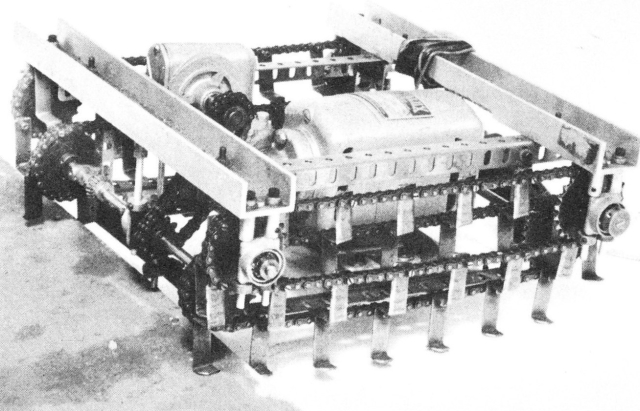
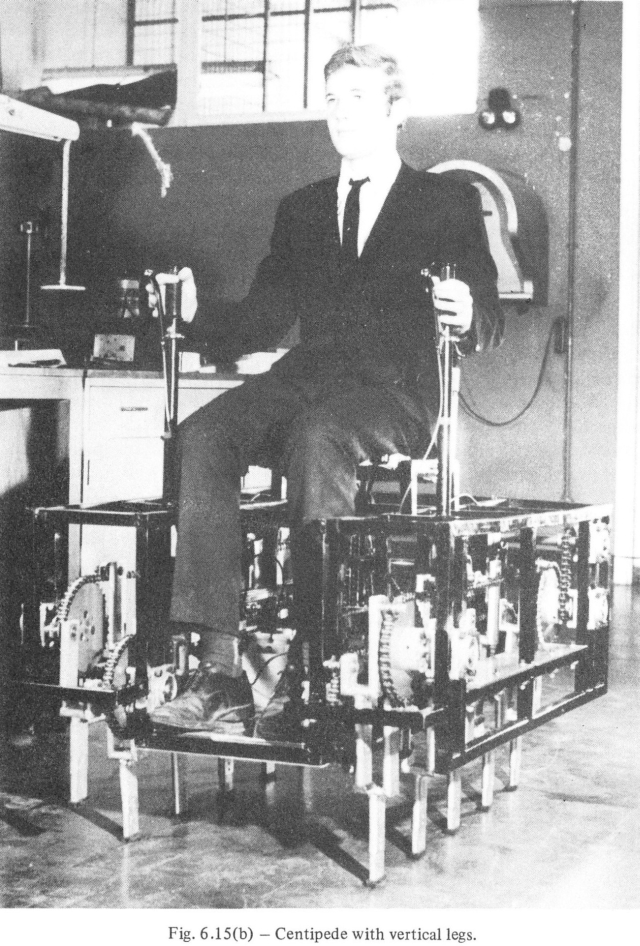
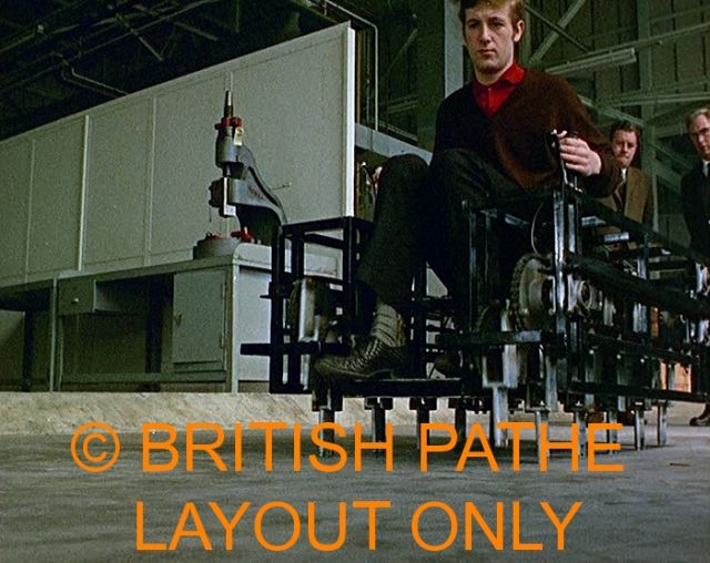
Model of Centipede.
The 'centipede'
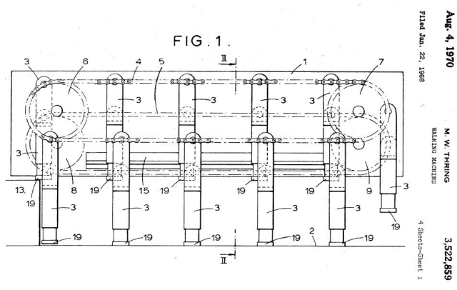
In the first model (Fig. 6.15(a) above) of the centipede the sprung legs were operated with two chains, one arranged half-way up the legs and one attached to the top of the legs, so arranged that the legs were always held vertically. Each leg is separately sprung and can have various types of feet on it (Fig. 6.16-not shown). However, a fundamental advantage of separate legs is that if one has a solid rubber pad for each foot, with no track on it at all, it still gives a good grip on soft ground because the front and rear edges of the foot act as the track. The actual weight is taken on a rail with a roller feed to the leg running on it.
Mechanical Elephant
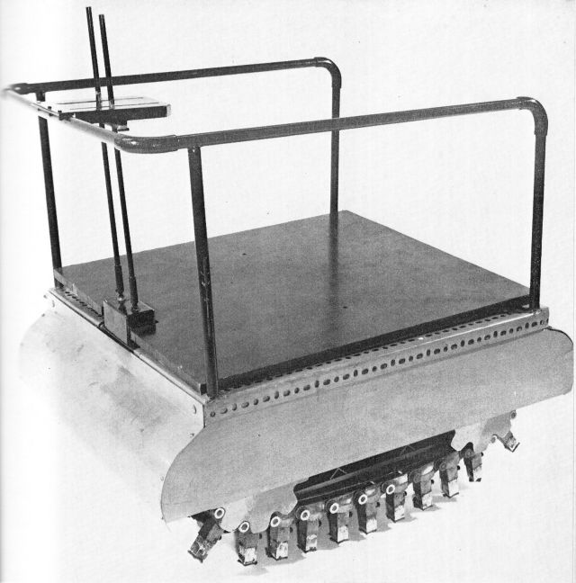
Above: Small-scale working model of mechanical elephant designed for rough- country load-carrying and a wide range of jobs required in developing virgin land for agricultural purposes. The legs of the 'centipede' track are individually sprung, giving the machine a capability of climbing vertical objects up to one-and-a-half metres high in the proposed full-sized version. The machine could also cross rivers and lakes.
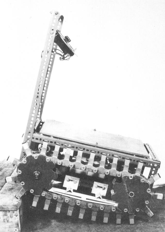
A study of this machine showed that it is not essential to have the legs moving vertically when they come down to the ground and they can come round a circle at the front and still give the same ability to climb stairs. The next version shown in Fig. 6.17 above can be described as a caterpillar track with legs. Each element of the caterpillar chain consists of T-shaped piece, joined to the next element by rollers at the corners of the crossbar of the T with the stem of the T forming the sprung leg. The two rollers run on rails which are concave upwards so that slightly more weight is taken on the middle feet than on the end ones, to make turning easier. The chains are driven by a hexagonal wheel at each end, with grooves in them that mesh with the rollers. If one has too few corners on these wheels there is too much variation in the speed of the track as the wheel rotates because of the difference in the radii of the circumscribing and inscribing circles of the polygons hence the wheels should be at least hexagons. The rail has to be located with its end at the radius of the circle traversed by the insides of the rollers.
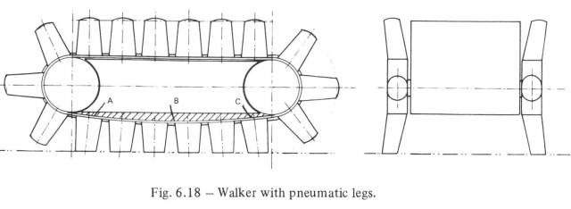
The other proposal (Fig. 6.18 below) has been specifically put forward for the problems of carrying tree trunks over areas where tree stumps are frequent, and for operating sugar beet or potato-extracting machines in a very wet season.
This has a single rubber track supporting low-pressure pneumatic rubber legs, which are preferably elliptical in cross-section, with the long axis in the forward direction, so that they can bend more easily sideways than backwards under load. The belt is driven by a toothed drum on each end, with the teeth meshing with grooves on the inside of the belt. The flat raised part of the teeth on the belt is coated with a low friction plastic and runs between the two drums on a convex-downward smooth steel rail, in the form of a wide plate, which takes the load.
Source: Robots and Telechirs, M. W. Thring, 1983.