1897 – Diving Apparatus – John and George Day. Little is known about the Day brothers. It is not currently known if the suit was built.
Images from the British patent GB189707105A.
Publication number US609418 A
Publication date Aug 23, 1898
Filing date Dec 22, 1897
Inventors Day And George Day
Be it known that we, JOHN DAY and GEORGE DAY, subjects of the Queen of Great Britain and Ireland, and residents of Maesteg, Glamorgan county, England, have invented certain new and useful Improvements in Diving Apparatus, of which the following is a specification.
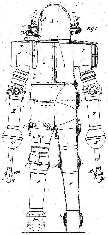
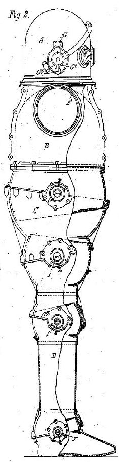
This invention relates to an improved divin g apparatus which consists of an inner noncollapsible jointed suit of improved construction and an outer flexible covering which serves to protect the suit-joints; and it may consist of an entire dress inflated with air, or of joint-coverings charged with suitable lubricant, or of an inflated body-dress, and leg, or leg and arm joint coverings charged with lubricant.
The invention has special reference to the joints of the suit, with the object of minimizing the friction and facilitating the movement thereof and obtaining a reliable water-tight joint, and to means of mechanically grasping objects under water.
……….
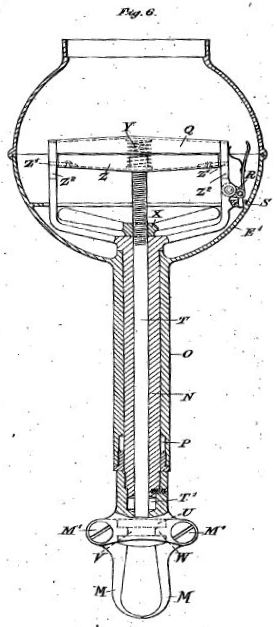
In the means of mechanically grasping objects under water (see Fig. 6) the forearmcasing E terminates in a hand-casing E, having a tubular extension 0, ending in a stuifing-box P. Projecting through the extension is a tube N, which within the casing E is fitted with a handle Q, and beyond the extension is formed with a stuffing-box T and is adapted to carry a pair of opposing grips M, pivoted at M and having inner projecting spurs W. Within the tube N is a rod T, which within the casing E is fitted with a handle Z and is screw-threaded and fitted with a wing-nut X, and beyond the stuffingbox T is formed with a head U, having notches V, adapted to engage with the gripspurs W. A spring Y is interposed between the handles Q Z, tending to separate the same and to open the grips M. The rod T can be reciprocated within the tube N to an extent determined by the engagement of projections Z on the handle end Z with slots Q in the handle end Q, which projections also prevent the rod T from turning Within the tube N. The tube N, rod T, and jaws M can be turned around or rotated about the axis of the rod T by turning the handles Q Z, and can be arrested in any desired position by a springcatch R, adapted to engage with holes S in a ledge projecting within the casing E. The grips M can be opened and closed by manipulating the handle Z and can be forcibly brought together by turning the nut X down the screwed portion of the rod T.
See other early Underwater Robots here.