jvkvkvkvhjkhj
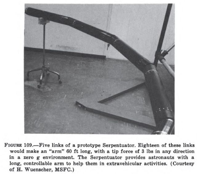
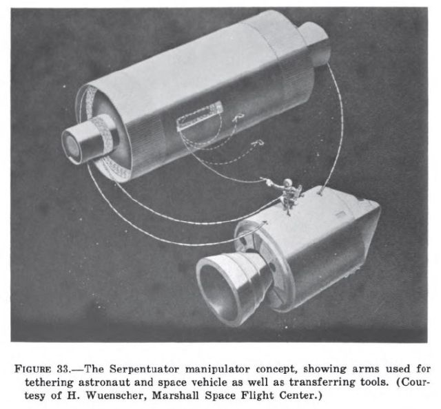
A rather unusual electrical unilateral teleoperator is the Serpentuator (Serpentine Actuator) under development at Marshall Space Flight Center (fig. 109 above). The Serpentuator consists of links several feet long separated by joints driven by electric motors, or, in one version, electrohydraulic actuators. With maximum deflections of about 20° per joint, the teleoperator can be coiled up in circular loops 20 feet in diameter and housed in the shroud of a Saturn rocket. Using switch controls at both ends of the Serpentuator, the operators can transfer tools, retrieve objects, aid astronauts, and perform other tasks in weightless space where positive controlled motion over distances greater than a few feet are difficult.
Crew and Cargo Transporters
Platforms for transporting men, and possibly cargo, fall into two general categories: those linked to the space-craft structures (serpentuator, trolley) and those capable of independent operation (LTV maneuvering work platform and Bendix EVA work platform).
Serpentuator – In 1968 a study was performed for NASA to determine the man/systems feasibility of using the MSFC-developed serpentuator as an EVA aid for film retrieval on the ATM mission. In this mission, the primary requirement for an EVA aid would be to assist the astronaut in transferring himself and seven fresh film magazines from the airlock-module egress hatch to each of the two ATM worksites–center work station and sun-end work station. After accomplishing this delivery task, the aid must assist the astronaut in returning himself and seven exposed film packages back to the hatch. The general requirements of the aid are that it possess the dynamics of motion are compatible with and controllable by a human operator (Bathurst and Mallory, 1968).
The Matrix study was an assessment of the degree to which these requirements were satisfied by the MSFC Serpentine Actuator or Serpentuator. This device consists of a series of connected, individually controlled and powered, articulated links with a roll-ring at the base and a payload cargo rack/ control station (CR/CS) at the tip. This device is depicted in Figure 4-7.
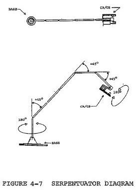
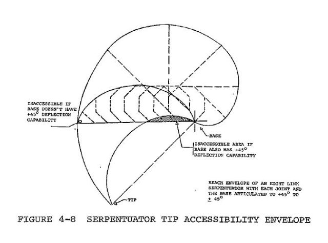
The serpentuator configuration selected for evaluation consisted of eight links and was 40 foot long and 4.5 inches in diameter. Each link was assumed to have a maximum deflection of 45deg in only one direction, and the base and CR/CS could be rotated +-180deg. This configuration was selected to be compatible with stowage requirements at launch.
An investigation of forces generated by serpentuators of varying lengths reported that a 54-foot long, 10-link configuration of the same diameter as that selected for study on the ATM could exert 9.5 pounds of force at the tip. A force of this magnitude is capable of accelerating a 500-pound mass (the approximate mass of the astronaut, film magazines, and CR/CS) at a rate of .025 fps2. If this acceleration is continued for a period of 20 seconds, the velocity of the payload will be approximately 4.2 fps.
In an effort to establish the geometric capability of the serpentuator, the surface of the geometric figure described by the tip when each joint is moved sequentially through its 45o and the base roll angle is held constant was plotted and is depicted in Figure 4-8. If this area is then rotated +-180deg about the base, the solid which is generated represents the volume which may be reached by the tip when no obstructions are present. Comparing this envelope with that of the ATM cluster, it was obvious that both film retrieval work stations and the airlock hatch were well within the reach envelope of the Serpentuator. It was, therefore, assumed that the Serpentuator was conceptually capable of performing as an EVA translation aid for ATM.
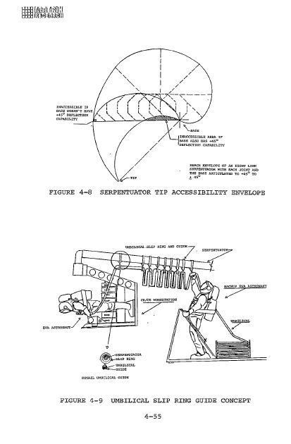
In the life support area, the primary problem was umbilical management. A system for controlling the umbilical was proposed and is depicted in figure 4-9.
Prime Vehicle Serpentuator System
The Prime Vehicle Serpentuator System is an advanced version of the serpentuator described in Section 4.4.1[see above]. This system, as applied to the prime vehicle class, is only in the conceptual stage of development, but most of the parameters described for the system used to support EVA also apply to the prime vehicle manipulator version. The astronaut control station would be replaced by a "robot" type subsystem containing video cameras, electrically driven bilateral actuator "arm" assemblies, etc. The man/machine interface problems would be minimized by designing these subsystems to closely resemble the human configuration (anthropomorphic and anthropometric). The control system would be more sophisticated than the EVA version, leaving few functions that would not be contained on pre-programmed modes. The astronaut would control and monitor/direct the system from a station within the prime vehicle with direct visual or video access
to the worksite, if necessary. Figure 5-11 illustrates this concept.
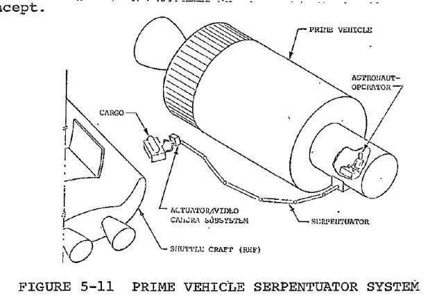
FIGURE 5-11 PRIME VEHICLE SERPENTUATOR SYSTEM
5-24
Source: SELECTION OF SYSTEMS TO PERFORM EXTRAVEHICULAR ACTIVITIES – Man and Manipulator – Contract # NA88-24384 – Volume 2, Final Report -Prepared for Marshall Space Flight Center – 9 April 1970.
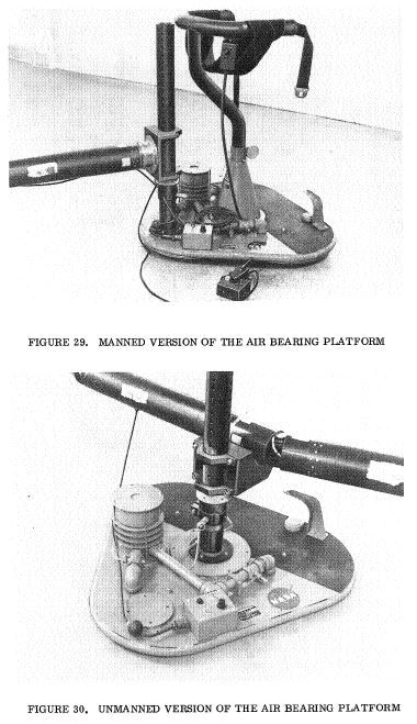
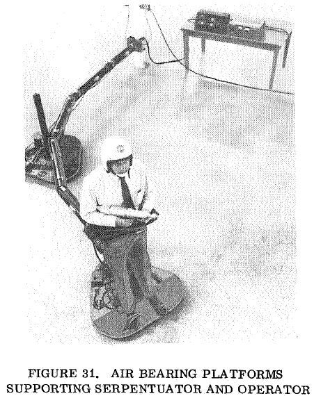
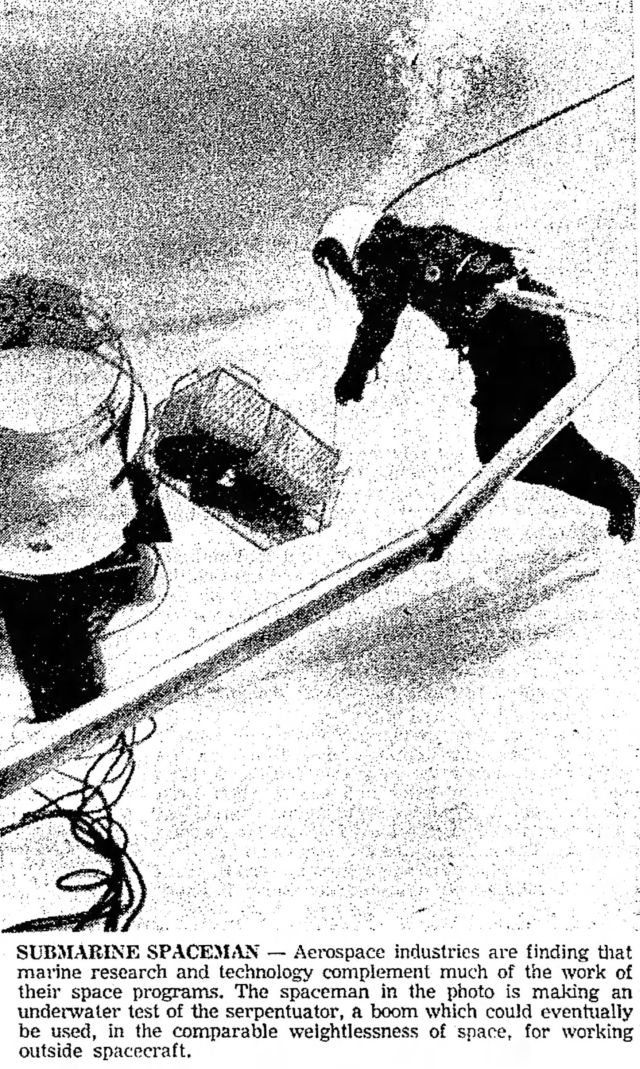
As the Serpentuator was to operate in a zero gravity environment, testing required devices such as air bearings or underwater testing as shown below.
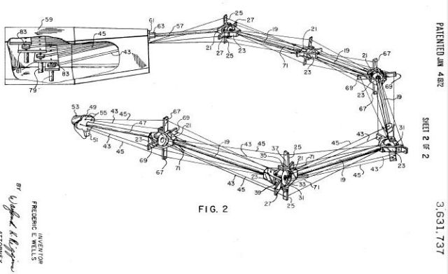
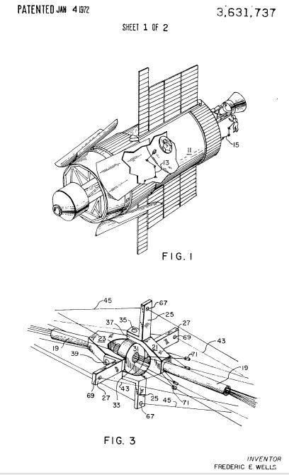
Publication number US3631737 A
Publication date Jan 4, 1972
Filing date Sep 18, 1970
Inventors Wells Frederic E
Original Assignee Nasa
Remote control manipulator for zero gravity environment
US 3631737 A
Abstract
A manipulator for handling objects remotely in a zero gravity environment comprising a plurality of rigid tubular sections joined end-to-end by flexible joints to form an articulated arm based at one end and free at the other end. Each of the rigid sections is manipulated by slender control cables attached to the respective sections and selectively extended and retracted. The cables are guided along the length of the articulated arm by means including the tubular sections, apertured disks at the flexible joints, and apertured lateral projections at the ends of the tubular sections. The free end of the articulated arm is provided with means, such as a grapple or an electromagnet, for holding an object being handled.
See other early Space Teleoperators here.
See other early Lunar and Space Robots here.