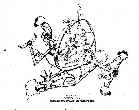
Concept O-9: Rendezvous by Manned Utility Tug
From a report compiled between 1959-61 and presented in 1961 are various concepts {Suffixed by 'O' for Orbital Rendezvous). This extract only selects those concepts that have a manipulator component.
WADD TECHNICAL REPORT 60-857
LAUNCHING AND ALIGHTMENT SYSTEMS FOR AERO-SPACE VEHICLES
Nelson T. Levings, Jr.
Cleveland Pneumatic Industries, Inc.
May 1961
Flight Dynamics Laboratory
Contract No. AF33(616)-6572
Project No. 1369
Task No. 13529
Wright Air Development Division
Air Research and Development Command
United States Air Force
Wright-Patterson Air Force Base, Ohio
FOREWORD
The work described in this report was accomplished by the Instrumentation and Control Division of Cleveland Pneumatic Industries, Inc., under Contract No. AF 33(616)-6572, Project No. 1369, entitled, "Launching and Alightment Systems for Aero-Space Vehicles, Task No. 13529.
This project was administered under the direction of the Flight Dynamics Laboratory, Directorate of Advanced Systems Technology, Wright Air Development Division [WADD], with Mr. Wallace Buzzard as Military Project Engineer, having superseded Lt. Don Austin in January 1960.
This report covers work conducted from June 1959 to January 1961.
Mr. Nelson T. Levings, Jr., was Contractor Project Engineer, assisted by specialized engineering personnel from each Division of Cleveland Pneumatic Industries, Inc.
CONTENTS
…………
30 Concept O-1: Attachment by Tail Hook Snag 62
31 Concept O-2: Attachment by Self-Guiding Probe Through Hoop 63
32 Concepts O-3 and O-4: Shock Mitigation between Two (2) Axially Aligned Vehicles 64
33 Arresting Gear for Storing Impact Energy for Subsequent Ejection Departure – Concepts 0-3 and 0-4 65
34 Concept O-5- Remotely Controlled Magnetic Contactor on Freely Swinging Cable 66
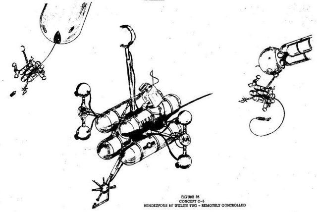
35 Concept O-6: Rendezvous by Utility Tug – Remotely Controlled 67
36 Concept O-7: Attachment by Mechanical Grappling Hook – Close Range 68
37 Thrust Compensator and Line Control for Concept 0-7 69
38 Concept O-8: Orbital Attachment by Self-Guiding Probe 70
39 Concept O-9: Rendezvous by Manned Utility Tug {See top for illustration] 71
40 Concept O-10: Rendezvous by Simple, Remotely Controlled Tug 72
41 Concept O-11: Long Range Attachment by Probe and Drogue – Heat or Light Sensitive 73
42 Latch Coupling for Concept 0-11 74
43 Mechanical Magnetic Ring Coupling for Concept 0-11 75
44 Concept O-12: Rendezvous of Axially Aligned Vehicles by Penetration 76
45 Concept O-13: Rendezvous by Surface Contact 77
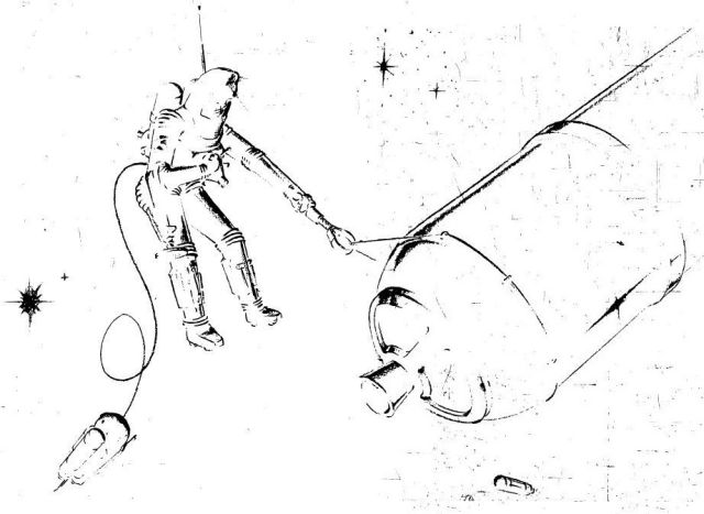
46 Concept O-14: Rendezvous in Matched Orbits by Man in Environmental Suit 78
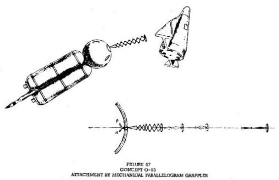
47 Concept O-15: Attachment by Mechanical Parallelogram Grappler 79
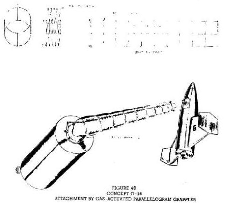
48 Concept O-16: Attachment by Gas Actuated Parallelogram Grappler 80
………..
2.3 ORBITAL RENDEZVOUS
Work during this phase of the project was faced with many unknowns. Initially, a cursory study was made in the area of orbital mechanics to determine what precision was required from thrust control during orbital rendezvous and if there might be a mass trade-off between shock mitigation and thrust control equipment. Again, airframe manufacturers and other agencies contributed to this effort.
The findings are summarized below:
a. The planes of the orbits of the target and intercept vehicles must be within minutes of arc.
b. The orbits must be matched in shape, size, and orientation within minutes of arc and, at time and point of rendezvous, the vehicles come together within close proximity.
c. The vehicles must be closely "in phase'" to affect rendezvous.
d. The vehicles, in the case of earth orbit rendezvous, should avoid lengthy exposure to the lower Van Allen radiation belt.
e. To make a rendezvous possible, corrective vernier rockets will have to operate within extremely precise limitations of thrust and cut-off times to bring relative velocity within acceptable limits.
f.* It was determined that, if each vehicle's velocity vector does not intercept the other's center of gravity on rendezvous, there may be a tumbling problem after contact.
To hold the mass of the shock mitigation equipment to an acceptable percentage of total mass, relative velocities were not to be considered over 35 ft/sec.
Parameters forming the framework for orbital attachment concepts include the same values applied ia-paragraph 2. 1; therefore:
a. 4 "earth" g's max. safe deceleration.
b. 1.5 safety factor applied to deceleration.
c. Vehicle gross weight approximately 20 tons (earth weight).
2.4 EARTH MANEUVERS
In this area, many concepts were submitted. However, since the problem of return to earth and landing are under detailed study in the Air Force as a portion of the Dyna-Soar development, no attempt was made to list a framework for concept formulation concerned with earth maneuvers.
* Any gravitational attraction between two bodies can be discounted with regard to bringing or holding them together. Eg: it takes only 2 (10)-5 radians/sec. rotation about a common C.G. to make two bodies of 100 tons each (whose C.G. 's are 100 feet apart)to balance the gravitational force holding them together.
3. SCOPE OF CONCEPTS
As the project progressed, the concepts submitted were categorized as to earth allghtment or departure, (labeled E-1, E-2, etc.), orbital attachment (0-1. 0-2, etc.), and lunar alightment or departure (L-l, L-2, etc.). They were sub-categorized as logically as possible, as to their nature — mechanical, electro-mechanical, multi-strut, etc.
5. 1 CONCEPTS SUBMITTED
The appendix shows the concepts submitted in pictorial form. They are separated into the three major categories shown above. Class I illustrates earth alightment and departure, Class II orbital rendezvous, and Class III lunar alightment and departure.
The sixteen (16) [only 6 Orbitals] most promising concepts as selected by WADD, are listed below:
Class I – Earth Concepts
……..
Class II – Orbital
3. O-1 Attachment by tail-hook snag.
4. O-2 Attachment by self-guiding probe through hoop.
5. O-7 Attachment by mechanical grappling hook — close range,
6. O-8 Orbital attachment by self-guiding probe,
7. O-11 Long-range attachment by probe and drogue — heat or light sensitive,
8. O-15 Attachment by mechanical parallelogram grappler. [This is the only illustrated concept shown here that made it through.]
Class III – Lunar Concepts
……..
NOTE: The 34 concepts eliminated from further study by WADD were rejected on the basis of (a) insufficient anticipated reliability, (b) lack of
confidence In state-of-the-art advances in that area and, (c) in the case of bags, balloons, and parachutes, cognizance by other WADD Laboratories.
Contributing Agencies:
1. Brunswick Corporation, Muskegon, Michigan
2. Cleveland Pneumatic Industries, Inc., All Divisions
3. Convair Astronautics Division, General Dynamics Corporation,San Diego, California
4. E. I. DuPont de Nemours & Company, Wilmington, Delaware
5. General Electric Company, Philadelphia, Pennsylvania
6. Goodyear Tire and Rubber Company, Akron, Ohio
7. Human Sciences Research, Incorporated, Arlington, Virginia
8. International Telephone and Telegraph Corporation, South Bend, Indiana
9. Jet Propulsion Laboratories, Pasadena, California
10. Lockheed Aircraft Corporation, Los Angeles, California
11. Lockheed Aircraft Corporation, Sunnyvale, California
12. National Aeronautics and Space Administration, Washington, D. C.
13. North American Aviation Corporation Missile Division, Downey, California
[No 14 in document]
15. North American Aviation Corporation, Los Angeles, California
16. Republic Aviation Corporation, Farmingdale L.I., New York
17. Wright Air Development Division, Wright-Patterson Air Force Base, Ohio
18. Dr. Waldo Kliever, Instrumentation Physicist, Cleveland, Ohio
19. Dr. Fred S. Singer, Radiation Physicist, University of Maryland
Document sourced from here.
See other early Teleoperators here.
See other early Lunar and Space Robots here.