The Iron Hand (Sourced from here and authored by Kerry Kirsch)
The Iron Hand was a robot that was developed by someone at Erie Engineering Company, 840 West Baltimore, Detroit, Michigan in the shadows of the old General Motors Building. Erie Engineering was owned by my grandfather, Frank Karl Kirsch, and specialized in Tool & Die designs for the automobile companies. The name "Iron Hand" sounds like it was inspired by a comic book hero. Back then, safety was not the priority that it is today. At a very young age, I recall hearing several stories of people regularly being injured, or killed in a stamping press. I won't go into the details, but I suspect that these reoccurring tragedies led to the idea of the Iron Hand to automate press work. I don't know the exact date of the photographs, but a car is visible in the background. I would be interested from hearing from someone the model and date to get a more accurate timeframe. I am guessing that they are from the late 1940s, early 1950s.
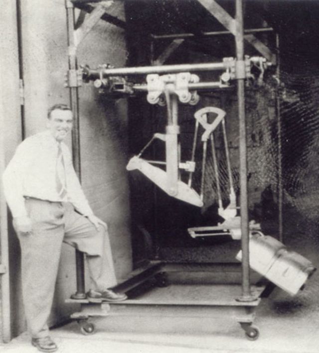
I suspect that the guy in the first picture was the man responsible for the design – he looks like a proud father. Unfortunately, I don't know who he is. I understand that the robot was hydraulically powered and the photos seem to show a hydraulic cylinder. The part in the gripper is a sheet metal stamping that appears to be part of a floor pan.
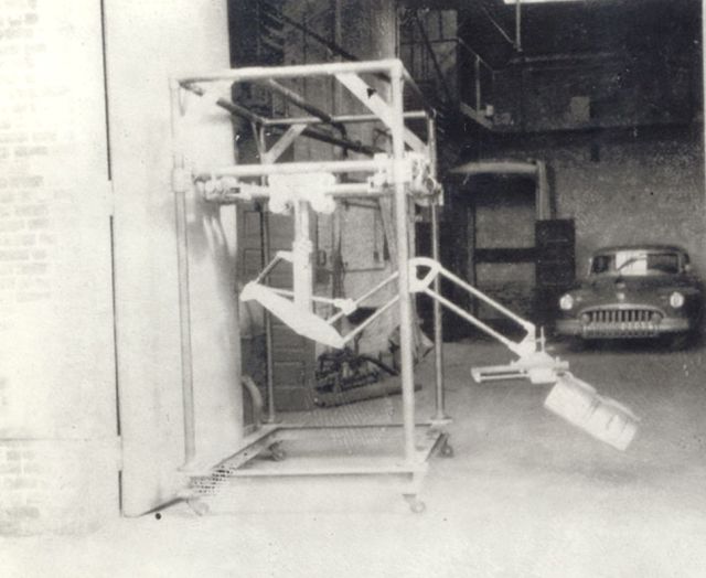
[RH/cyberneticzoo.com- Car appears to be an 1950 Buick bucktooth grille designed by Henry Lauve]
Back in those days, there were not a lot of options for controlling machines. The Iron Hand was controlled by a traffic light controller. Basically it is a timer that fired hydraulic valves. The mechanism for the arm is really quite ingenious. If you look carefully, you will notice a cylinder at the rear of the arm that imparts motion for reaching through a pair of links of unequal length to the upper rear arm. The arm consists of 4 rods connected at an elbow. In the elbow is a link that imparts motion from the upper rear rod to the lower front rod. It produces near perfect linear motion with only one cylinder.
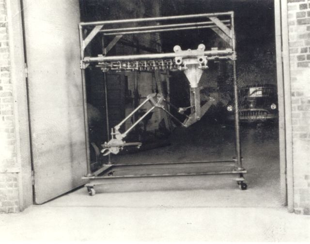
The above photo appears different from the other two. The robot is rotationally in a different position than in the previous photos and there appears to be some heavy chain attached to the frame that could not be seen in the others. I suspect this is because of the appearance of a waist axis. It’s not clear to me how this would have worked yet, but I'm sure someone has some ideas.
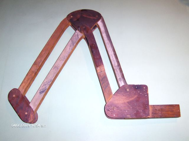
This is a photo of the prototype model I took recently. Under the triangular shaped plates at the top there was a short link that connected the lower left arm to the upper right arm. The link was broken off before I got the model. When I was in college, I measured it all up and wrote a Fortran program to model and plot how it would move. It produced near perfect linear motion. For my senior project at Lawrence Institute of Technology, I designed and built a similar arm that used 4 gears to replace the linking mechanism. I used a single DC servo motor with a harmonic drive gear reducer to rotate one of the rear arms at the base to achieve linear motion.
See other Early Teleoperators, Industrial Robots and Manipulators here.