The Robot Garguantua.
gar·gan·tu·a -n.
A person of great size or stature and of voracious physical or intellectual appetites. [After the giant hero of Gargantua and Pantagruel by François Rabelais.]
Like most, including myself, the true significance is lost in the title ("An Automatic Block-Setting Crane") and opening description of the original article published globally in Meccano Magazine, March 1938.
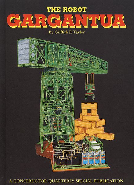
The original re-discovered documents now published in full book form.
In February 2013, Chris Shute contacted me about "Meccano Robot Gargantua".
Although I was aware of it, but must admit to: 1. trying to keep away from industrial robots, 2. mistaking the robot taking it for an elaborate 'crane' when I first saw it, 3. didn't study it well enough to realise it was programmable, 4. assumed someone else more recently attributed to word 'Robot' to it, and lastly, 5. I didn't take note of its early publication date. I'd like to think my research is normally very good, but incorrect pre-conceptions let me down.. Anyway, I've now been corrected and amazed after reading Chris' story of The Robot Gargantua re-produced below.
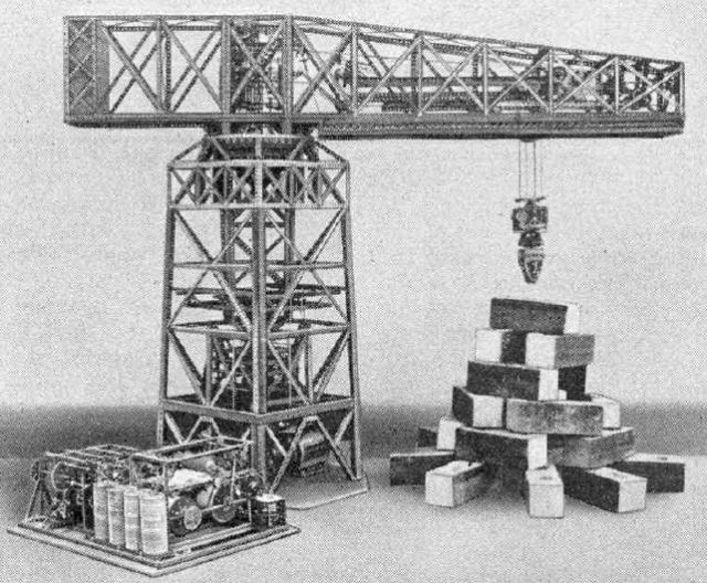
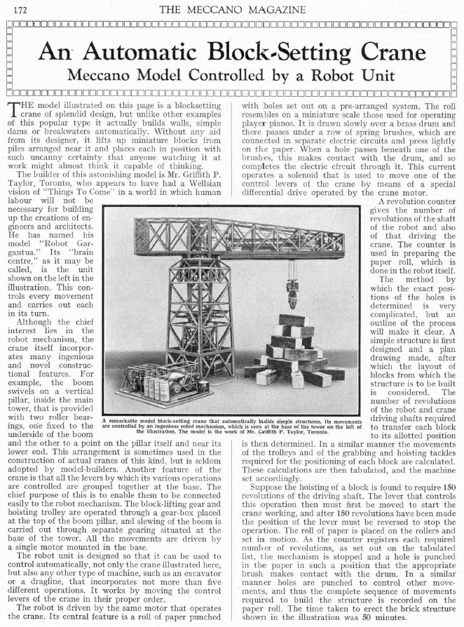
"In March 1938, the Meccano Magazine published a brief article describing an automatic crane of stunning complexity. Have a look at Meccano Magazine, March 1938 p172, viewable via: http://www.nzmeccano.com/MMviewer.php . A single motor drove all the motions of this monster machine, capable of building complex structures from wooden blocks automatically. From the original photograph, it was difficult to tell if Gargantua was even made from Meccano, or whether it could really do all that was claimed. Nobody had ever built anything so ambitious in Meccano.
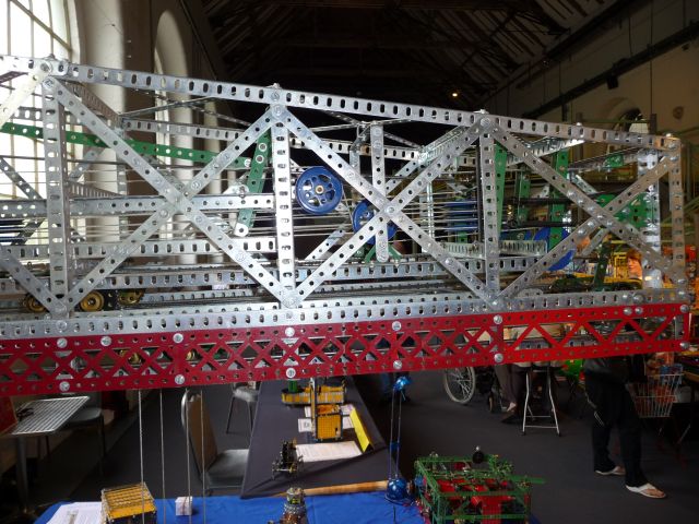
A full description and more detailed photographs lay hidden for nearly half a century until the Liverpool Meccano factory was demolished. Constructor Quarterly magazine published them in a book with notes by John Woollatt and the late Bert Love and Alan Partridge. The creator of Gargantua was a 21-year-old student, Griffith ‘Bill’ Taylor, the son of Scott’s Antarctic geologist. Bill died in 1996, having spent most of his life as a professor of civil engineering in Sydney, Australia. I built the ‘Robot’ programmer in June 1997 and met Bill’s widow and son. They encouraged me to build the whole crane, which I did during the following 12 months, about 400 hours work. Here's a picture of my reconstruction. The main features are:
• A single motor drives all motions.
• The grab can also rotate – power comes through the suspension cords.
• Mechanical limiters protect against over-driving.
• Control levers are situated at the base of the tower, not on the jib.
• No electronics are used apart from five solenoids.
• Sequences up to 3 hours long may be controlled by punched paper tape.
• Contains over 4000 washers, 300 collars, 200 gears and 100 pulleys.
• Non-Meccano parts: 4 bricks, 2 rollers, paper, wood, Ford Sierra fan motor.This is the only known complete reconstruction of Gargantua. I believe it was probably the world’s first truly programmable place-and-put robot. I feel it deserves a place in the history of robotics."
Chris continues in a second email.
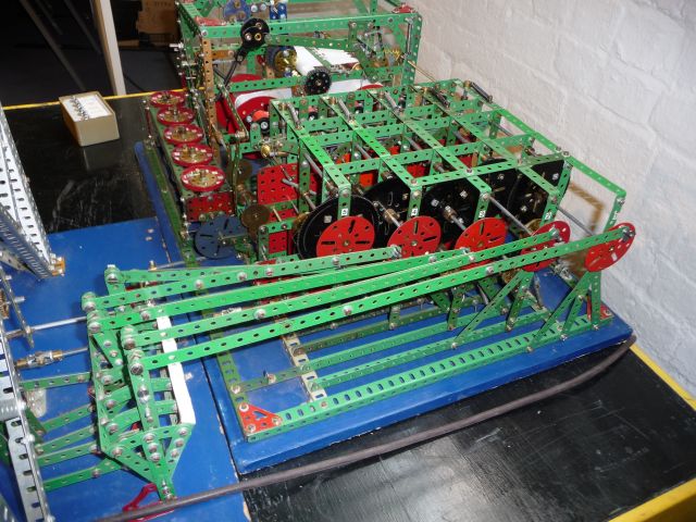
"I believe Bill Taylor submitted his article to Meccano Magazine late in 1937, after completing the machine. Roman numerals on his typed manuscript read "MCMXXXVII". His notes say the machine was "the result of 3 years "effort". The lead-in time for publication, and the surface mail time from Toronto to Liverpool would be considerable. Many mechanisms used in Gargantua are unique, and would have made good magazine features individually, at the time. It's puzzling why neither the magazine nor Meccano did not exploit Gargantua more. A Pathe Newsreel in July 1937 featured a Meccano loom, for example. Bill Taylor was born in August 1916, making him only 21 years old at the time of completing Gargantua, while still studying for his engineering degree. A remarkable acheivement. I've attached a picture of my reconstruction of the 'Robot' (as it was called) i.e. the device that pulls and pushes the pre-existing 5 control levers for the crane. Mine is the same size as the original. Each lever, top left, has a central neutral position and can move linkages to large dog-clutches in transfer gearboxes dedicated to each motion. The crane can be driven manually if the "Robot" linkages are disconnected. Then the lever ends must be squeezed to release any lever from its locked position, like an old semaphore railway signal lever. The 'Robot' is driven by the same single motor as the crane, via a driveshaft seen just right of the control levers. A Meccano Dog Clutch can disconnect this drive. A 5-digit counter, like an old electricity consumer meter, top right, is used to count the revolutions of the motor. My paper tape transport is slightly modified, using a capstan and rubber pinch roller, as in a reel-to-reel tape recorder, for constant paper speed, and therefore constant sized holes cut in the paper. When drive to the take-up paper drum is engaged, a light brake is applied to the feed drum, to keep the paper taut, and simultaneously, 5 wipers press down on the paper. When a hole arrives, a circuit is made to one of 5 solenoid coils. In the original device, these were home made (mine are 1960s standard Meccano parts). Power for the coils would originally have come from 4 large 1.5 volt dry cells (seen in the original magazine picture, about the size of a beer can). Mine use 12 volts from the motor supply. Lower right, I've added a cable to 5 pushbuttons for manually firing the coils during demonstrations. The (weak) solenoids do not actually engage any gears. Instead, they cause some of the main motor's power to act upon the control levers. Five differentials are driven from the motor through their RH half-shafts. A light brake on the LH half-shaft causes the diff cage to spin fast but with less torque, reduced still further by 1:5 gearing to a shaft above carrying a 2" rod in a Handrail Coupling. When the solenoid is energised, its core moves a rod left to jam this spinning rod, whereupon the LH half shaft will turn, overcoming its light brake. A 7:1 reduction to a shaft above moves a long linkage to the relevant control lever. After a quarter-turn of this shaft, a roller and sprung linkage will flick the solenoid rod right, thus releasing the differential cage, and movement of the control linkage stops. The quarter turns permit a sequence of Forward-Neutral-Backward-Neutral to be engaged for each drive. This seems an elaborate device to engage/disengage gears, but it does the job well, using only a single coil for each motion, requiring only 5 possible holes in the paper roll (3 1/2" wide, used for adding machines in the 1930s). Since the same motor drives both the paper and the crane, synchronisation is reliable. the distance between holes equates to the number of motor revolutions allocated for each operation. In practice, when any motion is required to arrive at an end-stop position, a few extra revolutions are given, to overcomes light discrepancies caused by slippage, for example of the string/pulley drives in the grab. All motions have mechanical limiters at their end-stops, so this is not a problem. The tower-buiding was planned on graph paper and a table of the required motor revolutions for each motion is calculated. (e.g.opening the grab requires 150 revs). From this, it is possible to write a 'program' of events (= paper holes) defined by motor revolutions starting at 00000. The program is transfered to the paper roll by disengaging the drive to the 'Robot' and cutting a hole over a wooden backing strip. For stacking 24 blocks, over 500 holes must be cut. An error of 1mm on the paper roll could translate into about 1"for a block's position. Editing/correcting of the program is done with sticky tape. But the system works. Errors are generally down to the 'software', not hardware."
Chris has an expanded version of his story published in 2007. see pdf here.
Historical Significance
I've largely left Industrial Robots out of my website, but I feel that The Robot Gargantua deserves to be recognised as the first currently known Pick-and-Place Robot built, so I'll add a page on the short history of Industrial Robots.
The First Industrial Robots:
The Babbitt invention of 1892, mentioned in many Industrial Robot timelines, is not a robot at all under any definition. The Babbitt Crane patent has no mention of anything automatic, is not programmable and is under manual control using hydraulics. Also no evidence of it being built, none that I've found, anyway. It appears to be an arm to grasp and remove hot ingots from a furnace. It may look robotic in today's terms, but that's as far as it goes.
- 1935-7 – The design, construction, and submitted manuscript of The Robot Gargantuan.
- 1938, March – The publication of The Robot Gargantua in Meccano Magazine.
- 1938, April – Pollard's Positional spray painting robot patent was filed in April 1938. This I would call a robot by current definition.
- 1939, August – Roselund filed his spray-paint robot patent – less of a robot than Pollard's due to the cam-drive nature, which , although good for repeatability, not good in re-programmability which defines an Industrial Robot.
- 1954, March – The Brit Cyril Kenward filed his patent , beating the Devol patent by a few months .
- 1954, December – Devol's patent filed and granted in 1961.
[Update 2 Mar 2012 – Pollard's son, Pollard Jr., produced an earlier patent for an automatic spray-painting machine. Filed on 29 Oct 1934, granted on 27 Aug 1940. From an article on parallel robotics by Ilian Bobey in 2003, the patent consists of two parts: (1) an electrical control system and (2) a mechanical manipulator. The control system consists basically of perforated films, the hole density of which is directly proportional to the speed of each motor. The mechanical manipulator, on the other hand, is a parallel robot based on a pantograph actuated by two rotary motors at the base. Pollard Jr.'s patent was eventually issued on June 16, 1942, but, in the meantime, a license was granted to the DeVilbiss company in 1937. In 1941, DeVilbiss, later to become the first industrial robot supplier, completed the first prototype under the direction of Harold Roselund. Roselund's spray painting robot, later patented in 1944, was not a parallel robot and used only the control system proposed by Pollard Jr. ]
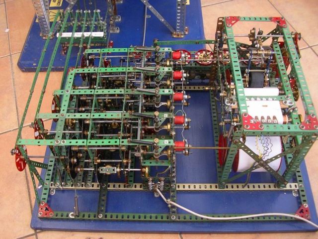
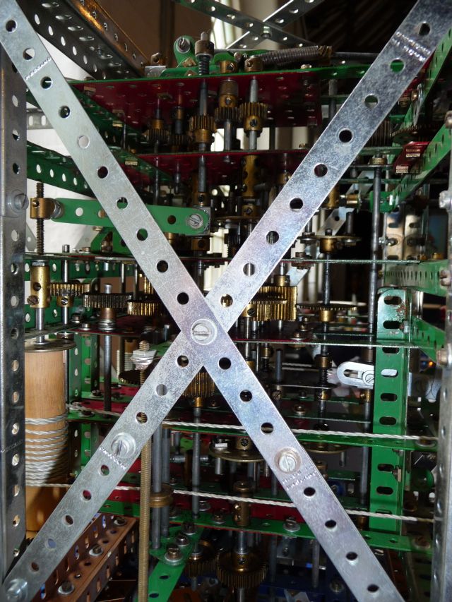
Control Unit – photo by Chris Shute.
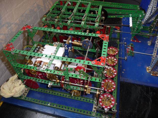
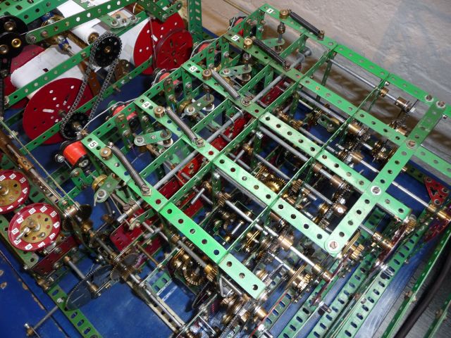
Above: Detail of Control Unit
.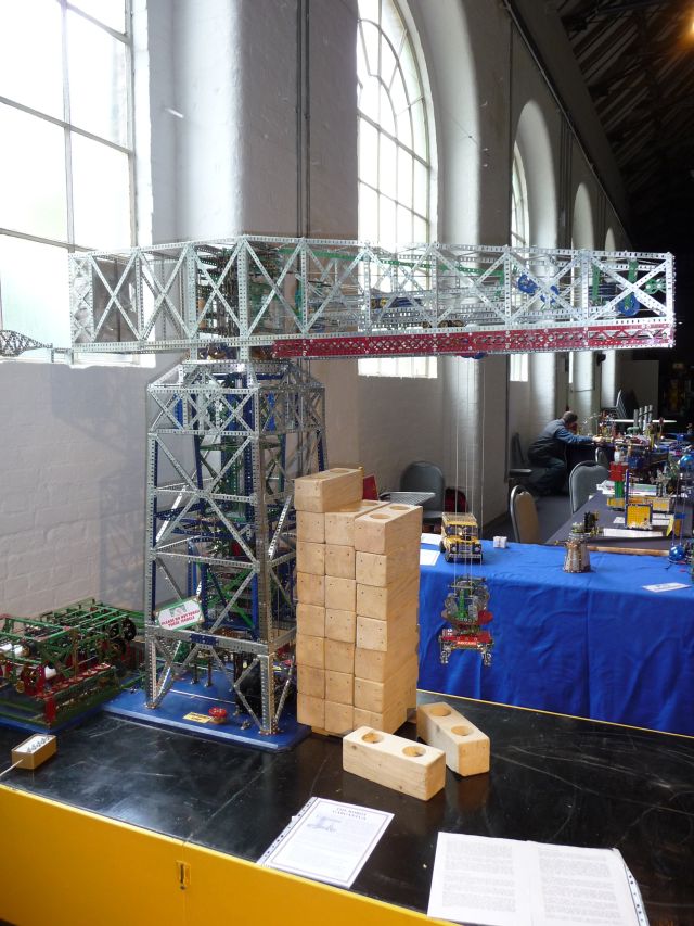
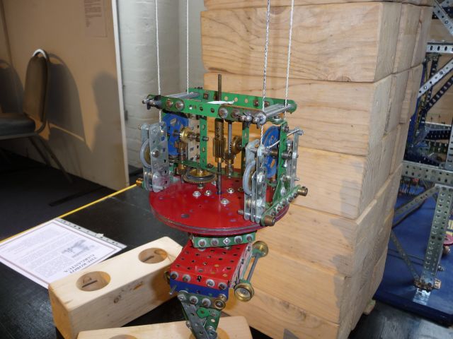
The gripper.
All photographs by Peter Haigh – see supersize originals here.
Thank you for including this magnificent Meccano construction- it and the earlier Meccano Differential analyser-
http://en.wikipedia.org/wiki/Differential_analyser
are amazing demonstrations of Meccano’s place in engineering history.
Of course the Meccano Manuals over the years have included Mechanical Men (Robots) – simple but always fascinating and fairly easy to build.
Tony.