.jpg)
A Radio Robot By EVERARD EDMONDS
Constructional Details of an Amusing Robot that Talks and Sings are Given in this Article.
Source: December 4th, 1937 PRACTICAL AND AMATEUR WIRELESS p337
MAN has created figures in his own image from the very earliest times. One recalls the Colossi of the Ancient World ; the marble statuary of Phidias, so perfect that it became imbued with life ; the figurehead that, bound to the bow of their ships, brought our Norse forefathers to this England ; and, finally, those re-creations of historical characters which have made Mme. Tussaud famous.
I remember, as a lad, becoming so enchanted with the Sleeping Beauty and her clockwork-heaving breast that I could scarcely be dragged away! And, on another occasion, when I first witnessed the speaking doll of a ventriloquist, my excitement knew no bounds, and I sent a shilling off post haste to learn this fascinating art —but, alas ! for my ambition, my patience failed to match it, and the power was never acquired.
Simple Construction
To-day, however, it is possible for almost anyone to construct in relatively little time, and with inexpensive materials, a most amusing Robot, whose active jaw and dancing eyes as he recites a poem or sings a song will entertain for hours!
First a suitable mask is required—one of those sold for the celebrations of Guy Fawkes Day will do very well. This may be mounted as shown in Fig. 2—the lower jaw having been first cut away. To the latter a T-shaped piece of paper may be glued, so that, when the jaw is fixed in position, the cross of the T stands behind use eyes, and may have drawn upon it two lovely black — er -pupils!
On the upright support are mounted the magnets and armature of a discarded electric bell. To the armature the lower jaw is now affixed, and we have the simple elements of our Talking Robot.
As the actual operating current will be relatively large, it is, necessary to construct the following relay system—a system well worth assembly, as it may be used for wireless control of models, selenium cell operation, etc.
Referring to Fig. 5, the wires leading from the Robot are connected to a relay R1, ..also made from a discarded bell, which closes the circuit of a two-cell cycle lamp battery (Fig. 6), thus operating the jaw and eyes of the figure. The contacts of this relay are the armature itself, and the pole pieces of the magnets, and, in order to prevent sticking, a small square of thin sheet-copper was soldered to the contact face of the armature.
Relay R1 is operated by R2 and a small 4.5 volt flashlight battery. R2 is the sensitive 5mA "Fulton" Relay sold by Electradix, Ltd., and it, in turn, is actuated by a valve. The latter may be any amplifying or power valve, and should have the requisite grid bias battery, as indicated in Fig. 5. The plate and H.T. + terminals go to the relay, and the grid and filament to the secondary of an ordinary intervalve L.F. transformer in the usual way.
A lead from the primary of the transformer is plugged in to the loudspeaker output terminals of a wireless receiving set (a portable receiver makes the whole assembly entirely independent of connecting wires to the mains, etc.) and it is now only necessary to tune in to a broadcast of speech or song when the Talking Robot will tell you all he hears A microphone connected to the pick-up terminals of the wireless set will enable you to talk through the figure so that, with a friend, you might give a most entertaining dialogue !
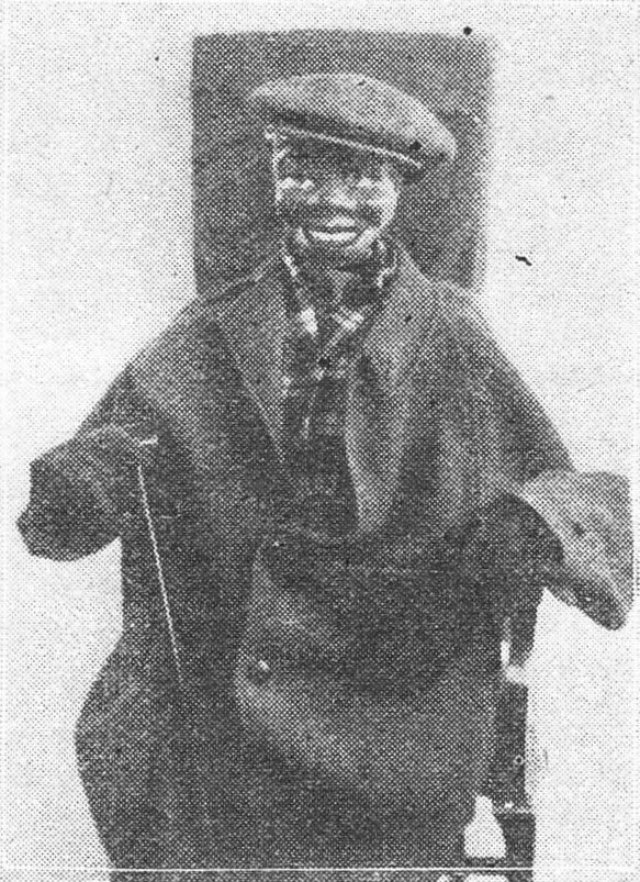
The figure may be completed with an overcoat and hat (Fig. 4) or in almost any way the constructor fancies. My own model sits on a chair the portable receiver being arranged underneath (Fig. 1) so that there shall be no interaction between the relay circuits and the aerial of the set. Condensers C1 and C2 have been included for this reason, but, of course, there is still a little interference, which can. only be entirely eliminated through the use of separate wireless sets for the sound, and for the operation of the figure—the latter set having the loudspeaker switched off.
Fig. 1.—The robot mounted on a chair with the portable set underneath.
Fig. 2.—Method of mounting the face mask and lower jaw.
Fig. 3. (left).—The battery and relay sections of the apparatus.
Fig. 4 (above).—The completed robot ready for work.
Fig. 5 (above).—The arrangement of batteries, components and connections.
Fig. 6 (right).—How the relays are covered to deaden sound.
Download pdf here