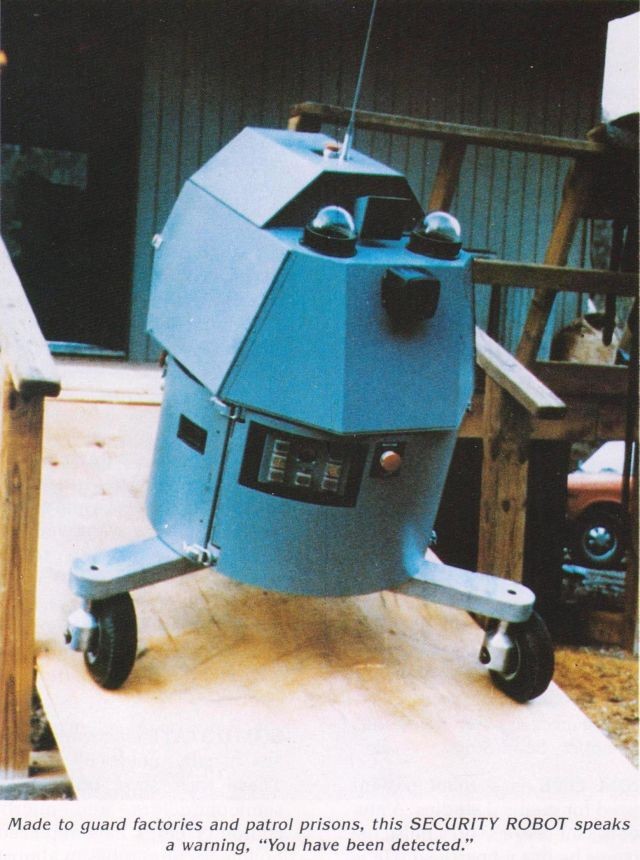
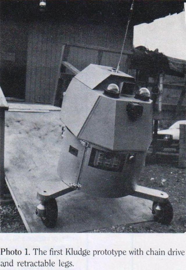
1983 – "Kludge" Omnidirectional Mobile Robot by John M. Holland.
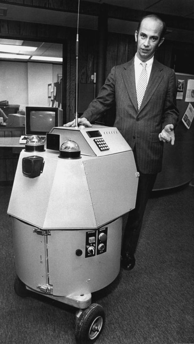
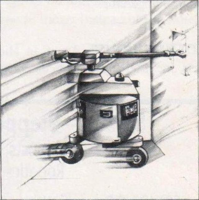
Kludge with legs contracted.
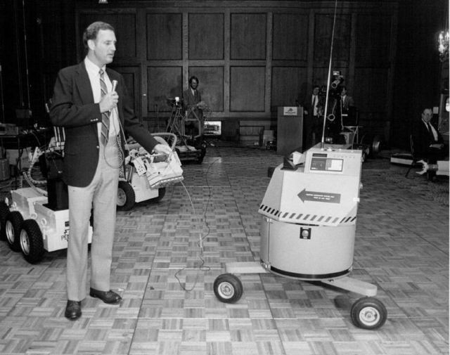
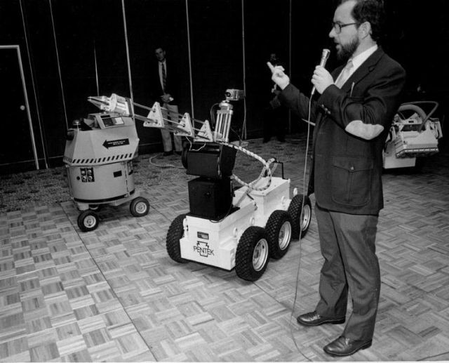
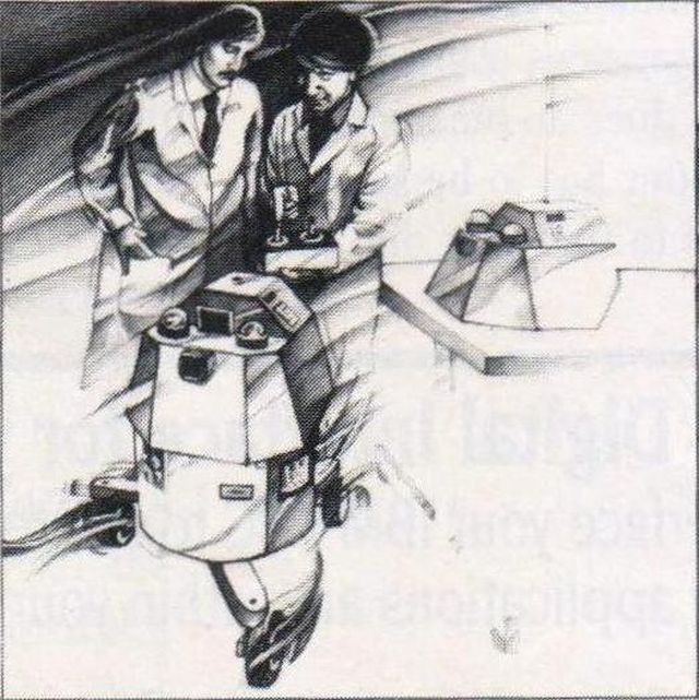
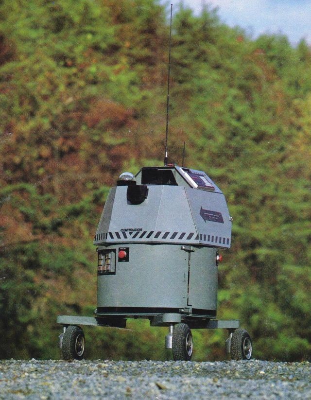
Kludge at a 1984 exhibition.

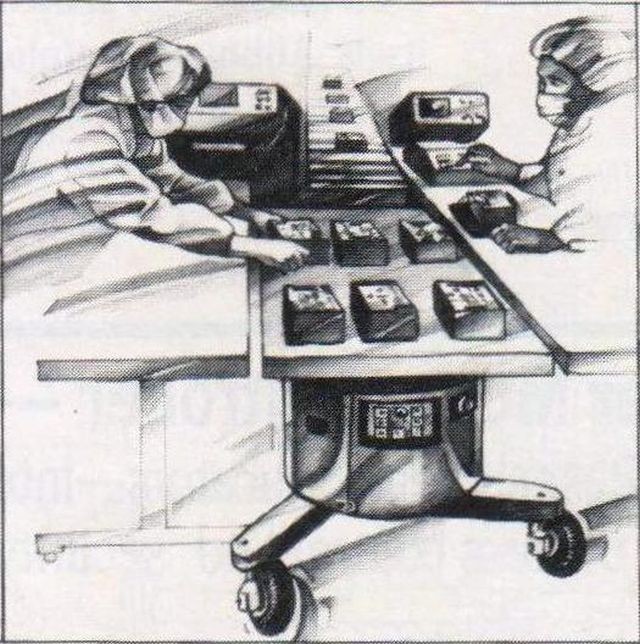
John M. Holland.
The focus in this post is on the unique mobility base, and not on its navigation and sensor qualities.
Patent Information:
Publication number US4573548 A
Publication date 4 Mar 1986
Filing date 23 Jul 1983
Priority date 23 Jul 1983
Inventors John M. Holland
Original Assignee Cybermation, Inc.
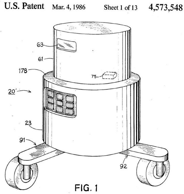
Mobile base for robots and the like
US 4573548 A
Abstract
A mobile base for robots or other devices requiring a transport mechanism is disclosed incorporating a plurality of wheels which are simultaneously driven and steered by separate drive sources so as to allow the mobile base to change direction without rotation of the mobile base. In an additional embodiment, each wheel is located on an extensible leg assembly which can be rotated to project outwardly from the mobile base and thereby provide additional stability to the base. This adaptive, retractable leg synchro-drive mobile base uses a third drive source to perform the extension and retraction of the leg assemblies and provides that the wheels maintain their orientation while extension or retraction occurs while the mobile base is in translation and that the wheel orientation returns to its previous state if retraction or extension occurs while the base is not in translation.
Source: Basic Robotic Concepts, John M. Holland, 1983.
Synchro Drive (Author)
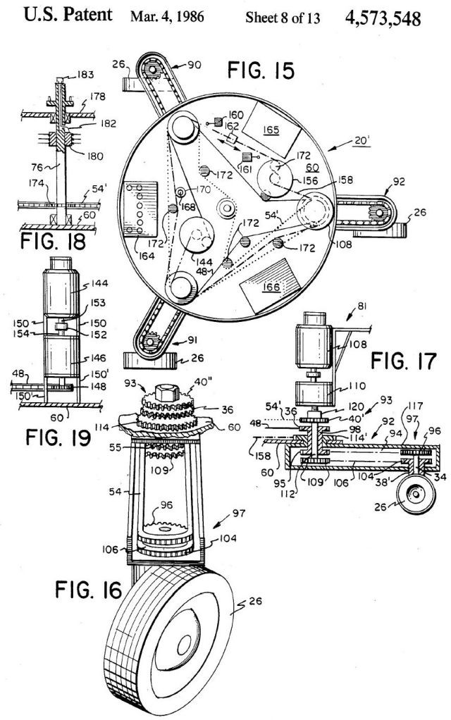
The synchro drive system shown in Fig. 3-18 features three or more wheels (in this case four) that are mechanically synchronized to each other for both steering and power. Synchronization can be accomplished by the use of chains (as shown), or by gears. Each wheeled "foot" assembly contains a 90° miter gear arrangement as shown in Fig. 3-19. The housing of the foot is driven by the steering chain, while the inner shaft is connected to the drive chain. The
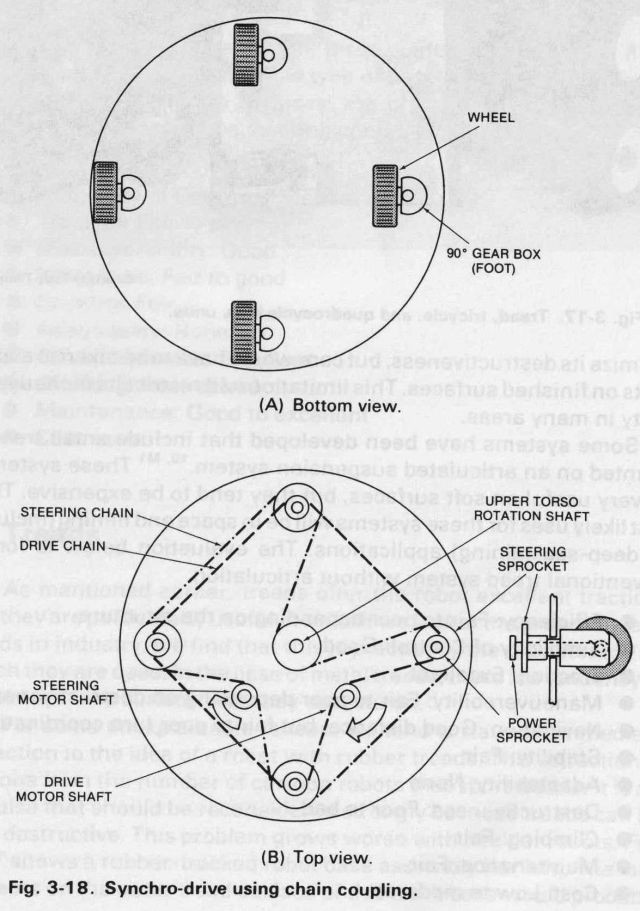
Fig. 3-18. Synchro-drive using chain coupling.
p148
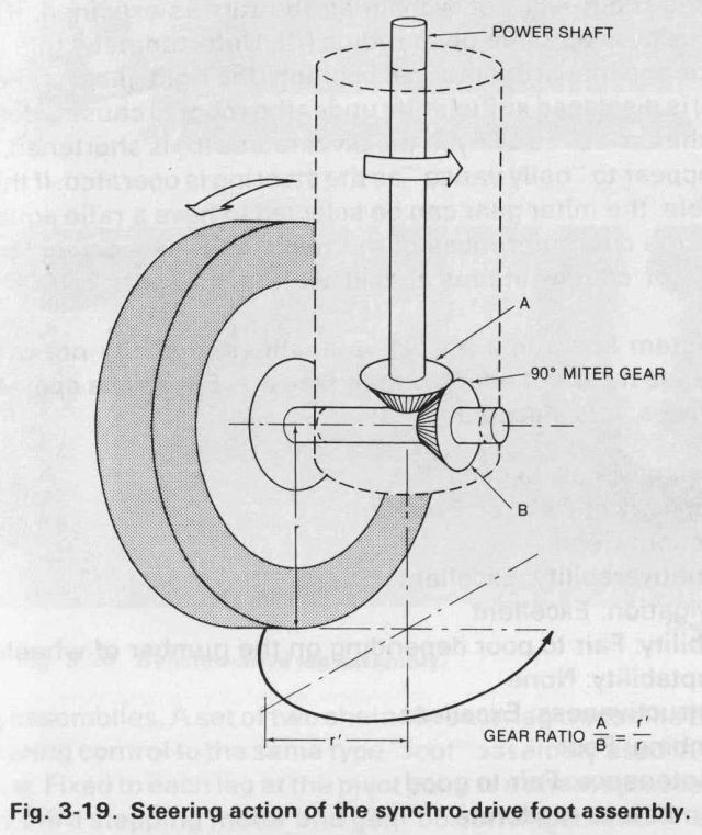
Fig. 3-19. Steering action of the synchro-drive foot assembly.
system offers some interesting characteristics when it is driven. Since the wheels steer together, the base does not change its rotational orientation when the robot executes a turn. For this reason, the upper torso of the robot (which contains the vision and ranging systems) is pivoted and mechanically linked to the steering chain. By driving the steering chain with a stepper motor (and gear reducer) the robot can execute very precisely controlled turns.
Notice that the miter gear (Fig. 3-19) must be on the opposite side of the power shaft from the wheel. This is because of the interplay between steering and wheel drive. If the power chain is stationary (the robot is not moving), and the steering chain causes the foot to execute one complete revolution, the wheel power shaft will experience the equivalent effect of one revolution in the opposite direction. With a miter gear having a ratio of 1:1 and located as shown, the wheel axle will revolve once in such a way that the wheel rolls around an arc as shown in the figure. This action is much easier on treated
p149
surfaces than having the wheel pivot about its center line. With the 1:1 ratio, the robot will not wobble as the turn is executed, if the wheel radius (r) is equal to pivot radius (r'). Unfortunately, this may mean that in the inboard rotational position (the right-most wheel in Fig. 3-18A) is displaced sufficiently under the robot to cause a deterioration of the zone of stability. If the pivot radius (r') is shortened, the robot will appear to "belly dance" as the steering is operated. If this is objectionable, the miter gear can be selected to have a ratio equal to the ratio of the circumferences of the two circles associated with r and r'. This of course means that it will be the ratio of the two radiuses.
The system has some attractive qualities, but it is not overly stable because it cannot adapt to steep terrain. For robots operating on flat surfaces, it is a good alternative.
• Efficiency: Fair to good
• Simplicity of Control: Excellent
• Traction: Good
• Maneuverability: Excellent
• Navigation: Excellent
• Stability: Fair to poor depending on the number of wheels
• Adaptability: None
• Destructiveness: Excellent
• Climbing: Poor
• Maintenance: Fair to good
• Cost: Low to moderate
Adaptive Synchro Drive with Retractable Leg Assemblies
The adaptive synchro drive represents a compromise between the complexity of a walking robot, and the simplicity (and poor stability) of the synchro drive. The requirement that led to this design was to provide a robot that could negotiate relatively steer ramps, and that could climb over mild curbs without falling over. The solution was to add a degree of adaptability to the synchro drive. This was to be accomplished in the simplest possible manner, and the result is shown in Figs. 3-20, 3-21, and 3-22.
The adaptive synchro drive has the same basic power and steering chain arrangements in the base as did the original system, except that at the positions where the wheels were, there are now pivoted
p150
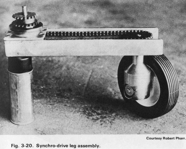
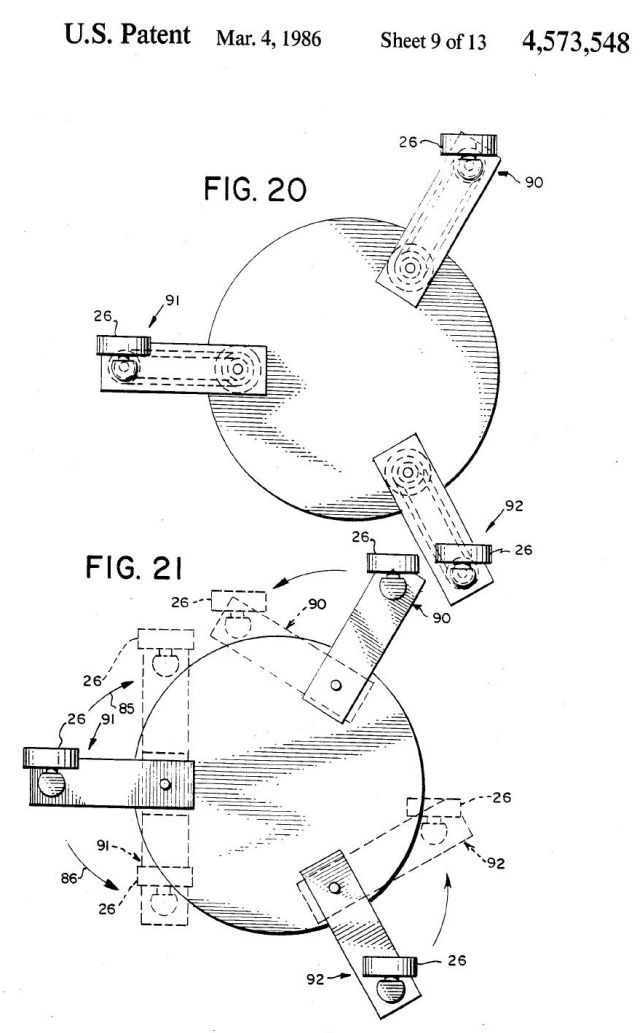
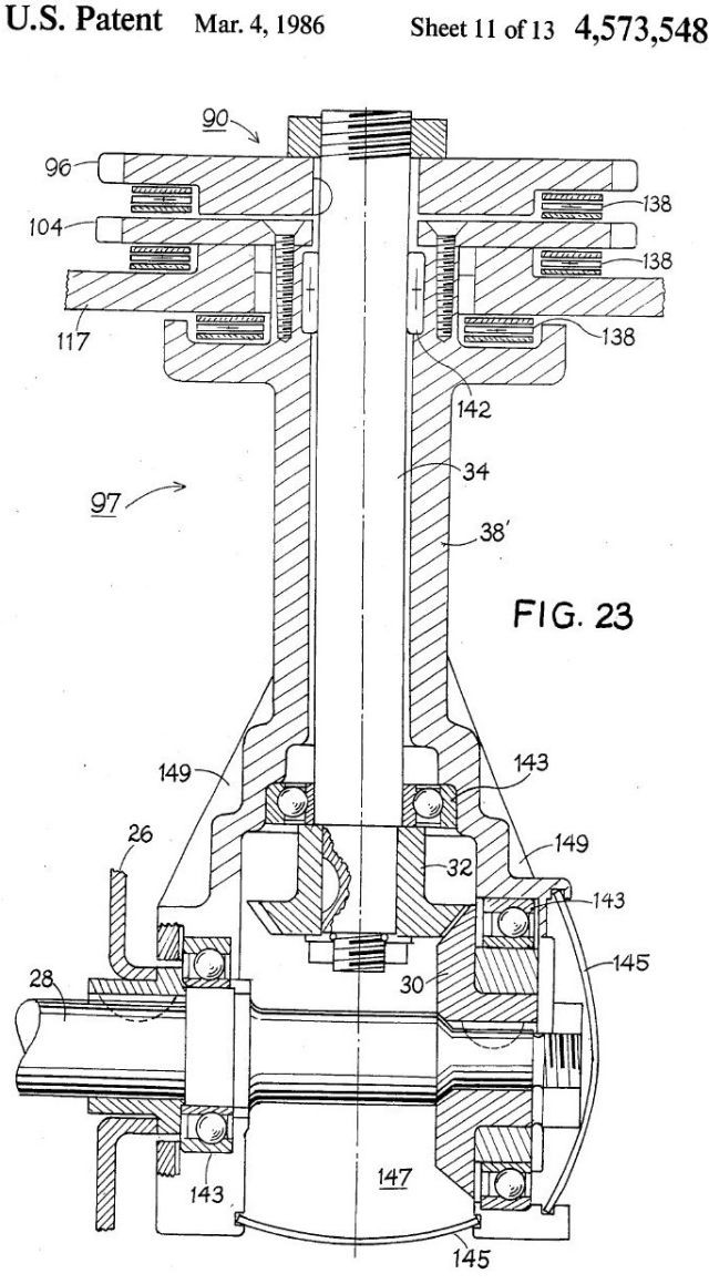
Fig. 3-20. Synchro-drive leg assembly.
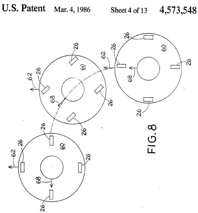
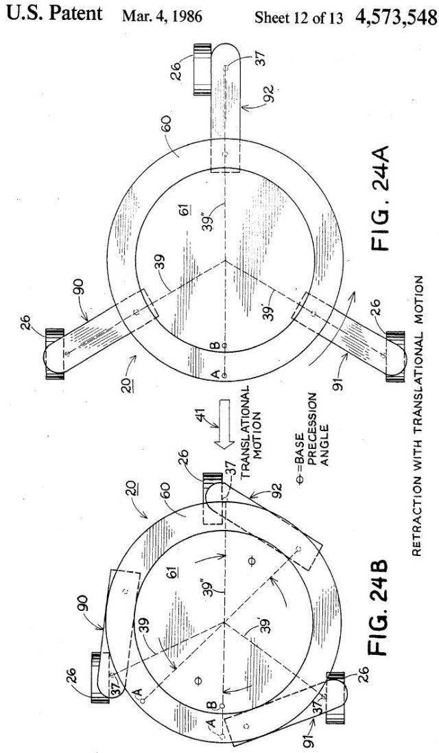
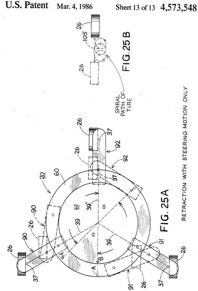
leg assemblies. A set of two chains in each leg transmits the drive and steering control to the same type "foot" assembly used in the synchro drive. Fixed to each leg at the pivot point is a chain sprocket connected to a third stepping motor and gear box arrangement. The power and steering shafts run concentrically through this sprocket into the leg. This arrangement allows the legs to rotate about their pivots (Fig. 3-23), thus changing the effective area of the base. As the legs rotate, the linkages are such that the wheels continue steering in the original direction. Since there is no capability of steering the wheels individually, they cannot be caused to "toe in" during collapsing. For this reason, a certain amount of rolling motion is required to allow this action to take place without damaging the surface on which the robot is running. To accomplish this, the action of the retraction (collapse) motor can be locked to the main drive motor. If the legs must be retracted in a short distance, the robot may have to roll forward and backward once or twice. Alternatively, it can execute a continuous turn with the drive motor turned off. Another disadvantage to this system is that the base orientation cannot be controlled. Thus if the robot approaches a load with the legs extended, it must make do with whatever the orientation of the legs might be. A modification to the steering chain may be added to overcome this problem.
151
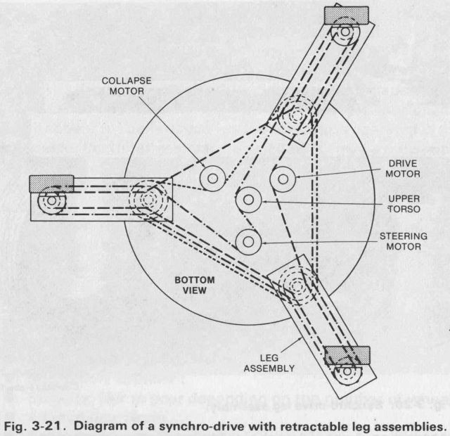
Fig. 3-21. Diagram of a synchro-drive with retractable leg assemblies.
This modification would consist of three movable idlers taking up chain slack between the wheels. In the normal position of these idlers, the wheels would all steer in the same direction. In the other idler position the wheels would all steer tangentially and the robot base could pivot on its own axis. Unfortunately, this reduces the simplicity and economy of the design.
Like the synchro drive, this carriage can steer through 360 degrees without moving. This eliminates the need for backing up. There are several advantages to avoiding this maneuver, including the elimination of rear facing obstacle detection systems and the elimination of polarity reversing circuitry on the main power motor. This second factor improves efficiency since solid-state polarity reversing circuitry always induces some power loss.
This whole arrangement is of course an elaborate compromise, but it was one that satisfied our needs. The lack of independent wheel steering control was traded off for the simplicity of control and economy of having only one drive and one steering motor. The two main sacrifices that had to be made were in the area of efficiency and maintenance.
p152
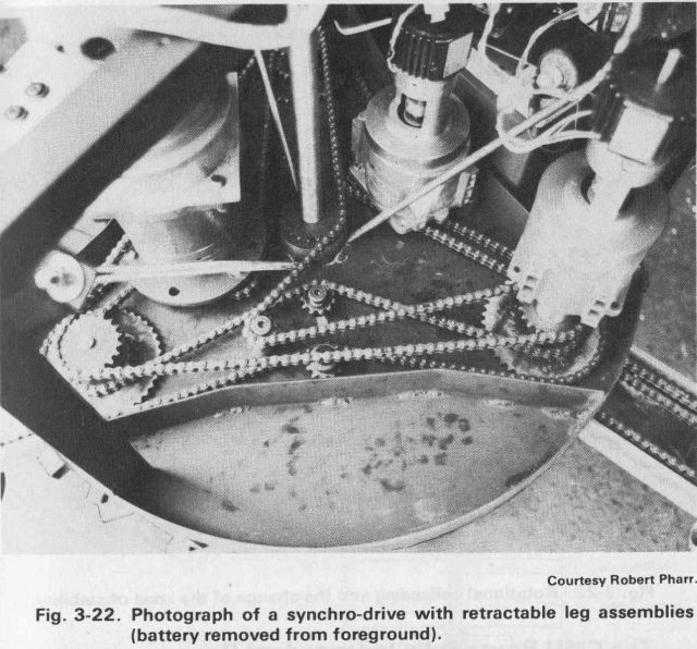
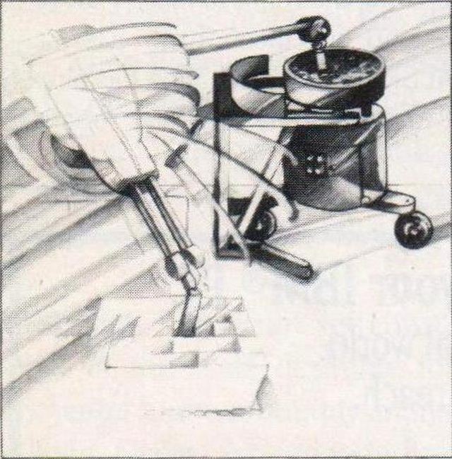
Fig. 3-22. Photograph of a synchro-drive with retractable leg assemblies (battery removed from foreground).
My experimental version of this system (named "Kludge") has been very successful, and the efficiency is better than expected. With 8-inch diameter tires and its legs extended, Kludge can climb over 4 X 4-inch timbers (actually 3.5 X 3.5 inches). My totally unbiased assessment of this approach is:
• Efficiency: Fair to good
• Simplicity of Control: Excellent
• Traction: Good
• Maneuverability: Excellent
• Navigation: Excellent
• Stability: Fair with legs retracted, excellent with them extended
• Adaptability: Adaptable to ramps and small single steps
• Destructiveness: Excellent with precautions mentioned above
• Climbing: Poor
• Maintenance: Fair (I hope)
• Cost: Moderate
p153
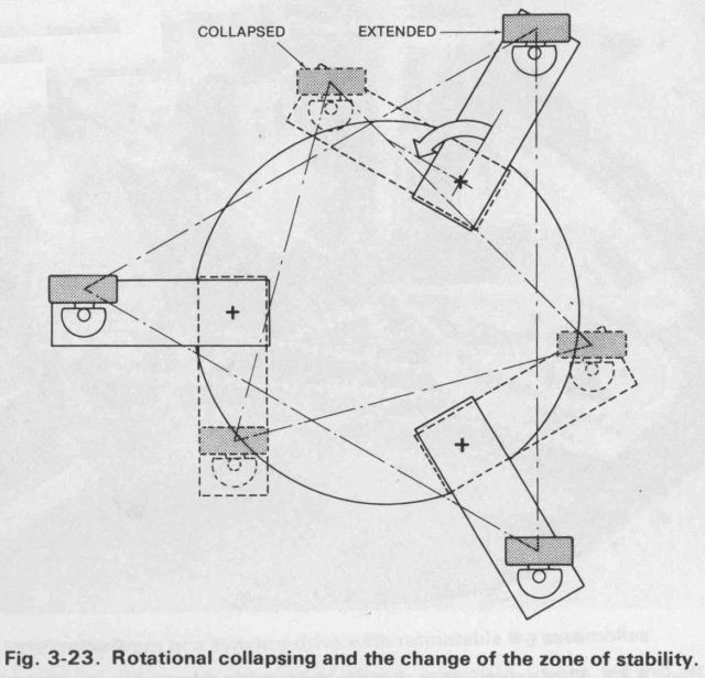
Fig. 3-23. Rotational collapsing and the change of the zone of stability.
ACKNOWLEDGMENTS
….I would also like to thank Mr. Robert Pharr of Roanoke, Virginia, whose mechanical expertise brought the mobile robot "Kludge" from a concept to a reality. Thanks must also go to my technician, Mr. William Grady Spiegel, for his support in breadboarding many of the circuits associated with Kludge and other systems discussed in this book…
JOHN M. HOLLAND
The Old Robots conveniently has a pdf of this article.
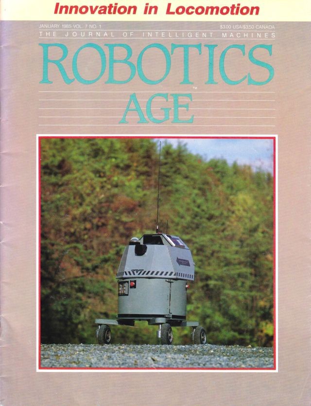
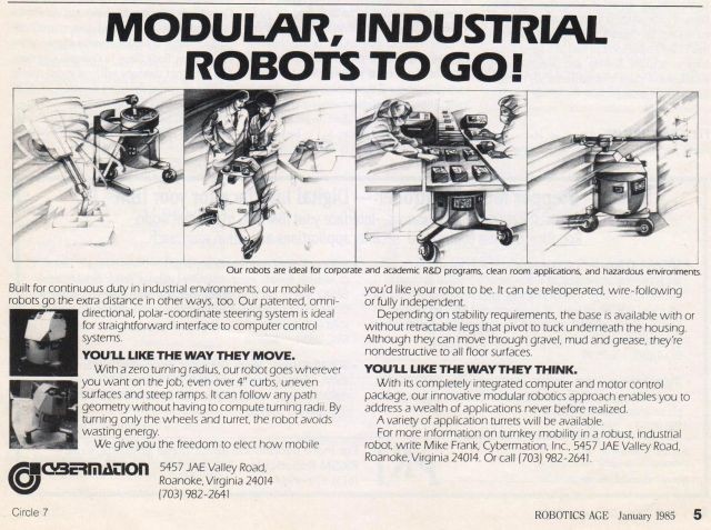
Source: ROBOTICS AGE January 1985 [edited]
RETHINKING ROBOT MOBILITY
John M. Holland
Cybermation, Inc.
When human beings attempt to solve a problem, they tend to match successful past solutions to the new situation. While this problem solving technique is extremely helpful in day-to-day situations, it can be misleading when we attempt to solve unique new problems. The trouble is that this whole conceptual process is so unconscious that we are unaware of the assumptions we make along the way. The problem of robot mobility is an excellent example.
When we start thinking about robot mobility systems, we immediately catalog the solutions to mobility problems in other fields. Most present-day mobile robots use a version of the mobility system originally designed for either a tricycle, a wheelchair, an automobile, a tank, an all-terrain vehicle, a wagon, or a combination of these. In some cases, the designer has turned to nature for inspiration and the result may resemble a spider or even an elephant.
Many mobile robots are well adapted to the problems they are designed to solve. For example, robots like the Ohio State University (OSU) Hexapod or the Odetics Odex I walker are required for certain rough-terrain applications. In fact, an article by R. B. McGhee, et. al. (see references) shows that walking robots may actually be more efficient than wheels or treads on soft surfaces. Still, it is very important to realize the original problem for which the technique was developed.
Attempting to apply existing vehicle designs to robots quickly points out the difference between the intelligence and sensory capabilities of a robot "driver" and a human operator. The robot driver will be a relatively stupid, nearly blind computer. Expecting a robot driver to perform the classical parallel parking maneuver for an automobile is optimistic in the extreme.Solutions based on animal models have an additional problem since animals are constructed from different materials than those available for the robot. For example, muscle tissue provides both an excellent lightweight servomechanism, and compliant springiness that can be used to store and recover kinetic energy.
SPECIFICATIONS
Before designing a robot mobility system, we must determine the robot's intended capabilities and make several trade-offs for cost vs. performance.
The first major trade-off is between walking and rolling. While a walking robot can go almost anywhere, it will tend to be very complex mechanically, difficult to control, expensive to build, slow, and (on finished surfaces) relatively inefficient. Some of these difficulties can be eliminated, but only at the expense of making others worse. Depending on the applications, the ability to climb stairs, rubble, and undefined obstacles, may outweigh all other considerations. On the other hand, it may be more economical to replace stairs in the robot's environment with ramps, thus making a rolling robot acceptable.
There are always restrictions on the robot as well. These restrictions include the width and height clearance available, the maximum weight, the damage that it can be permitted to inflict on its running surface, etc.
p26
…….
As the robot design progresses, it is sometimes necessary to back up and modify or subdivide the original performance envelope. For example, two models of the robot may become necessary to fulfill all requirements, or perhaps an ability may be dropped rather than modify the robot's operating environment.
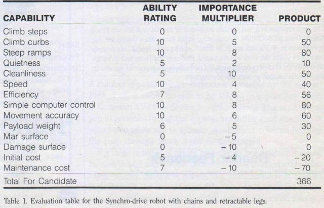
The example used in Table 1 evaluates applications we had in mind for our Cybermation robots and is an approximate evaluation of our first prototype. These robots would be expected to perform teleoperated and autonomous functions in demanding industrial applications, including explosives factories, clean-rooms, and nuclear reactor buildings. Thus, as reflected in the table, initial cost is not as important as the maintenance costs and reliability. The ability to climb steps was dropped in favor of requiring ramps and lifts.
THE SYNCHRO-DRIVE
The base consists of three wheel assemblies located on retractable legs. We call this the Synchro-drive since a set of chains is used to synchronously steer and drive all three wheels. The robot has three sets of motors, gear boxes, and chains; one for driving the wheels, one for retracting and extending the legs, and one for steering the wheels. Additionally, the steering chain is connected to a spine shaft running up through the center of the base. The robot's turret is mounted on a flange attached to this shaft, and rotates with the shaft in such a way that the turret always points in the same direction as the wheels.
This configuration gives the Synchro-drive some interesting capabilities. For example, the base does not rotate as the robot executes a turn. Not only does this save energy (by not requiring rotational acceleration and deceleration of the base), but it also allows the robot to maintain a sense of direction, by measuring the angle of the turret and base. One of the greatest advantages of the Synchro-drive is that steering and drive commands represent a pure polar coordinate reference system. This greatly simplifies navigation.
Furthermore, since the Synchro-drive has a true zero turning radius, it does not need reverse. This means that rear-facing sensors, and two (expensive) quadrants of the drive motor control can be eliminated.
p28
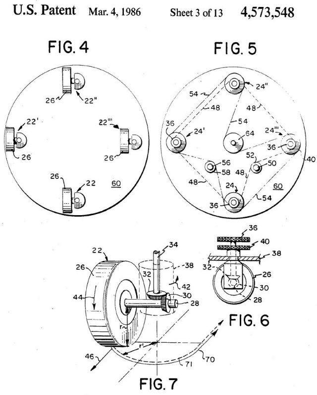
Finally, the wheel assembly is designed to allow turns without translation. This was accomplished by off-setting the wheel from the center of the steering axis and placing its driving gear in such a way as to impart a rolling action during steering. The robot can thus turn in place, without damaging carpets, tile, or wood floors.
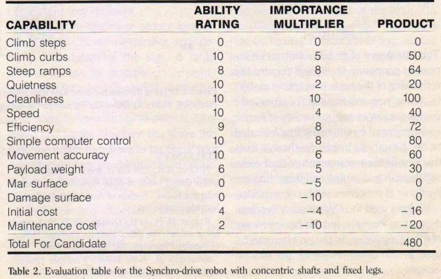
Table 2. Evaluation table for the Synchro-drive robot with concentric shafts and fixed legs.
The Synchro-drive approach evolved after many (informal) cycles through the evaluation process just described, and yet the approach still had short-comings at the point shown in Table 1.
The prototype (nicknamed Kludge) showed that the basic mode of movement was largely superior to other modes being considered, but the chains were a real problem. First, chains don't like to operate in a horizontal plane, and at least 180 degrees of engagement or purchase is required on each sprocket. This meant that many idlers had to be installed, which lowered efficiency and increased costs. Secondly, the chains stretch over time and must be adjusted. Additionally, the chains took up a lot of room and forced the robot's center of gravity to be higher than necessary. As a general rule, chains are noisy and dirty by nature. Finally, the wheels had to be realigned each time the chains were adjusted or tightened.
Each of these problems could be lessened by one measure or another, but the approach kept coming up short of our goals.
USING SHAFTS
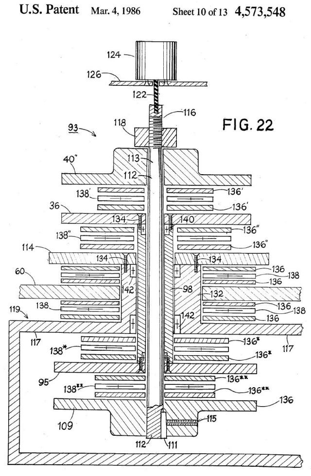
The problem then became how to build a robot that had all the good qualities of Kludge but was clean, reliable, easily assembled and repaired, had a lower center of gravity, and required no realignment. It wouldn't hurt if the new approach was (in the jargon of the patent office) clearly novel as well. This would allow us to obtain patent protection for the engineering investment.
The solution was to use a unique combination of concentric shafts and bevel gears. With this configuration, the moving parts could be enclosed inside hollow tubes comprising the robot frame members. This eliminated pollution, and greatly reduced maintenance. Accurately keyed gears kept the steering in alignment at all times.
The second production prototype (K2A) contains only a handful of different types of bearings and gears that are used repeatedly throughout the design. Furthermore, the new approach allows the batteries, drive motor and gear box to be slung between the leg members, lowering the center of gravity. By doing this, and by extending the fixed legs slightly beyond the edge of the base, the robot is about 80 percent as stable as the first Kludge prototype with its legs fully extended, and about 160 percent as stable as the first prototype with its legs retracted. Although an extensible-leg version using concentric shafts is planned, the cost savings on the current model outweigh the loss of high-end stability, at least for most current applications.
The result of these improvements is shown in Table 2. Notice that for the relatively small loss of stability, the savings in other areas are substantial. As an additional advantage, the maneuver required for extending and retracting the legs was eliminated.
CONCLUSION
The emergence of mobile robots as an important economic reality will require the rethinking of the basic precepts of mobility. These new mechanical "beasties" will encompass an enormous variety of forms, each governed by the niche it is intended to fill. Exactly as in nature, those robots that best fill the requirements of their niche will flourish and evolve, and those that are hastily or ill-conceived will become extinct.
We have used the Cybermation Synchro-drive as an example, but the basic process of fitting a solution to the problem can be used in the development of any robotic system.
p30
REFERENCES
McGhee, R.B., KW. Olson, and R. L. Briggs "Electronic Coordination of Joint Motions for a Terrain Adaptive Robot." Society of Automotive Engineers, Inc. Warrendale, PA.
Raibert, M. H., et al. "Dynamically Stable Legged Locomotion." The Robot Institute, Carnegie-Mellon University, Pittsburgh, PA. September 1981.
Holland, J. M., Basic Robotic Concepts. Howard W. Sams Publishing Co, 1983.
"Kludge" was a prototype. It evolved into the successful K2A then the K3A, subject to another post.
The company Cybermation became Cybermotion, and now KineLogic.