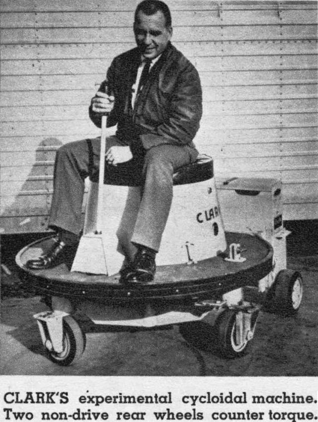
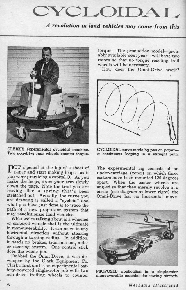
CLARK'S experimental cycloidal machine. Two non-drive rear wheels counter torque.
Source: Mechanix Illustrated, April 1963.
CYCLOIDAL PROPULSION
A revolution in land vehicles may come from this new invention which can provide perfect maneuverability.
PUT a pencil at the top of a sheet of paper and start making loops—as if you were practicing a capital O, As you make the loops, draw your arm slowly down the page. Note the trail you are leaving—like a spring that's been stretched out, Actually, the curve you are drawing is called a "cycloid" and what you have just done is to trace the path of a new propulsion system that may revolutionize land vehicles,
What we're talking about is a wheeled or castered vehicle that is the ultimate in maneuverability. It can move in any horizontal direction without steering through a turning radius. In addition, it needs no brakes, transmission, axles or steering system, One control stick does the whole job.
Dubbed the Omni-Drive, it was developed by the Clark Equipment Co, Clark's first unit is an experimental battery-powered single-rotor job with two non-drive trailing wheels to counter torque. The production model—probably available next year—will have two rotors so that no torque reacting trail wheels will be necessary.
How does the Omni-Drive work?
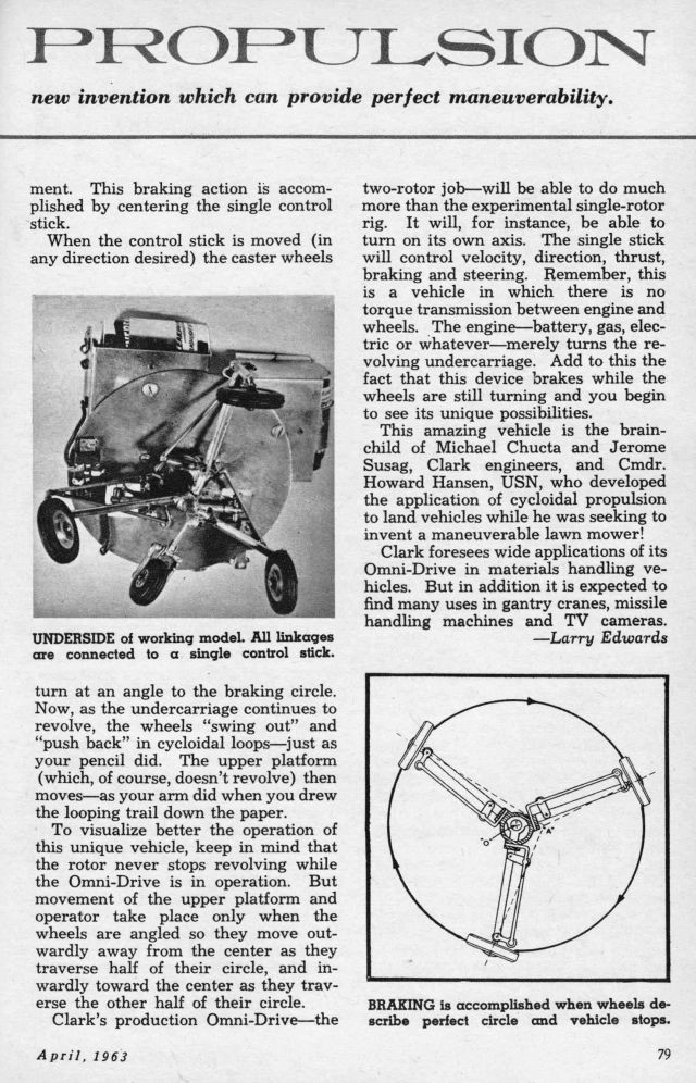
The experimental rig consists of an under-carriage (rotor) on which three casters have been mounted 120 degrees apart, When the caster wheels are angled so that they merely revolve in a circle (see diagram at lower right) the Omni-Drive has no horizontal movement, This braking action is accomplished by centering the single control stick.
When the control stick is moved (in any direction desired) the caster wheels turn at an angle to the braking circle. Now, as the undercarriage continues to revolve, the wheels "swing out" and "push back" in cycloidal loops—just as your pencil did, The upper platform (which, of course, doesn't revolve) then moves—as your arm did when you drew the looping trail down the paper,
To visualize better the operation of this unique vehicle, keep in mind that the rotor never stops revolving while the Omni-Drive is in operation, But movement of the upper platform and operator take place only when the wheels are angled so they move outwardly away from the center as they traverse half of their circle, and inwardly toward the center as they traverse the other half of their circle,
Clark's production Omni-Drive—the two-rotor job—will be able to do much more than the experimental single-rotor rig, It will, for instance, be able to turn on its own axis, The single stick will control velocity, direction, thrust, braking and steering. Remember, this is a vehicle in which there is no torque transmission between engine and wheels. The engine—battery, gas, electric or whatever—merely turns the revolving undercarriage. Add to this the fact that this device brakes while the wheels are still turning and you begin to see its unique possibilities.
This amazing vehicle is the brainchild of Michael Chucta and Jerome Susag, Clark engineers, and Cmdr, Howard Hansen, USN, who developed the application of cycloidal propulsion to land vehicles while he was seeking to invent a maneuverable lawn mower!
Clark foresees wide applications of its Omni-Drive in materials handling vehicles. But in addition it is expected to find many uses in gantry cranes, missile handling machines and TV cameras.
—Larry Edwards
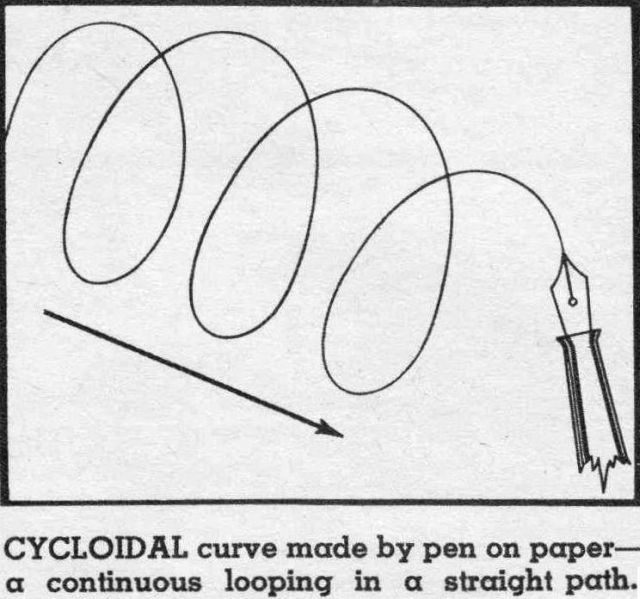
CYCLOIDAL curve made by pen on paper—a continuous looping in a straight path.
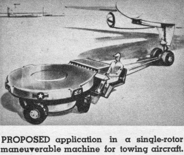
PROPOSED application in a single-rotor maneuverable machine for towing aircraft.
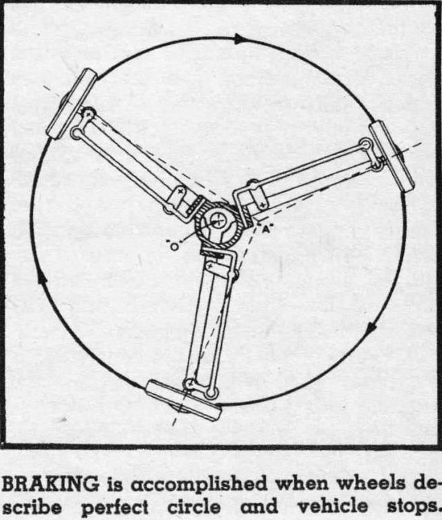
BRAKING is accomplished when wheels describe perfect circle and vehicle stops.
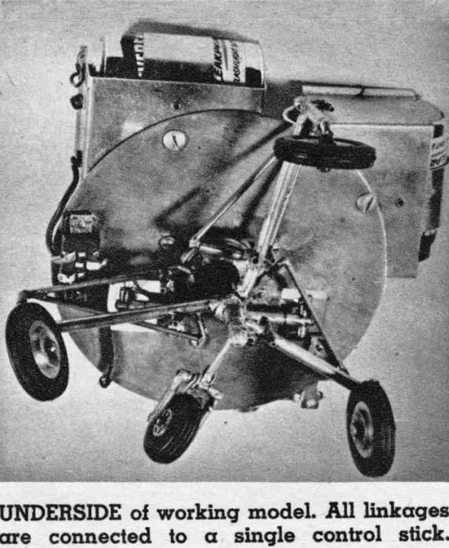
UNDERSIDE of working model. All linkages are connected to a single control stick.
Source: THE HILLSDALE DAILY NEWS, Monday, January 14, 1963
Vehicle Shows New Type Of Propulsion
DETROIT (AP) — A new type of land propulsion was to be demonstrated and discussed today at the opening of the 1963 convention of the Society of Automotive Engineers.
With it, you can drive a vehicle in any direction — even up and down, like a bird. It conceivably could some day give you an automobile you could edge into a parking place—sideways.
It is called "Cycloidal Land Propulsion" and it grew from a Navy officer's search for a power lawn mower he wouldn't have to haul and tug to mow around 40 trees on a place he'd rented in Falls Church, Va., in 1958.
It needs no brakes or clutch or transmission or axles.
. . .
The inventor is Cmdr. Howard C. Hansen, now commanding officer of the Navy's Patrol Squadron 49, and he told the engineers today how Cycloidal Land Propulsion grew from his desire for a lawn mower that would power itself circularly around those Virginia trees.
Clark Equipment Co. is adopting Hansen's propulsion method to its industrial trucks (the kind that shuttle crates and boxes hither and yon in warehouses and factories.
. . .
Michael Chucta, engineer in the advanced products section of Clark's industrial Truck Division at Battle Creek, says a vehicle utilizing such propulsion "is remarkably simple to manufacture" and foresees its use by various special job vehicles.
It isn't yet ready for your automobile, or vice versa, and may never be. Top speed of a vehicle thus propelled presently is calculated at 10 miles per hour, and it multiplies the bumps.
Cycloidal Land Propulsion utilizes wheels — one to any number, but three currently is considered the most satisfactory alignment. They are mounted (something like casters on a dresser to a circular undercarriage that is whirled around by the vehicle's power plant.
. . .
The wheels bite outward and inward from center at various points on their circular rotation to give a vehicle propulsion.
Steered to run in a true circle they halt the vehicle and act as brakes, since the tires would have to be dragged along if it were moved while the wheels were running in a true circle. It stops itself thus.
In forward movement, the wheels point outwardly as they traverse half the circle, and inwardly, toward the center, as they traverse the other half.
. . .
A Naval aviator, Hansen designed his original cycloidal or omnidirectional vehicle for control with a stick similar to that used in an airplane. The vehicle moves in whatever direction you move the stick, and the further you move the stick the faster it goes in that direction.
A vehicle using only three wheels (or one revolving cycloidal unit) requires a trailing pair of wheels attached to the rear of the vehicle to absorb torque and keep the vehicle from tending to spin in the direction the whirling wheels are spinning.
But Chucta told his fellow engineers that a vehicle using two units, each spinning in opposite directions, needs no other wheels to remain stable and translate (which means move in any direction).
Such a vehicle also can yaw, throw one end around to where the other was, or swing its front or rear to and fro.
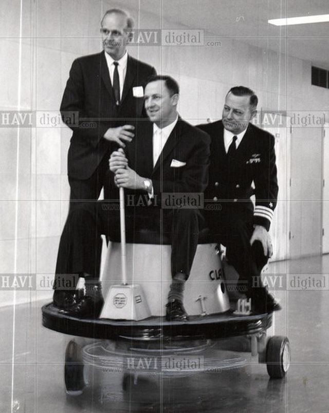
Caption: Three men, from left to right, Jerome R. Susag, Michael Chucta, and Commander Howard C. Hansen, most responsible for its development in land vehicles showed how cycloidal propulsion worked at the Society of Automotive Engineers meeting.
Patent Information:
Publication number US3016966 A
Publication date 16 Jan 1962
Filing date 12 Oct 1960
Inventors Howard Clair Hansen
Original Assignee Howard Clair Hansen
Omnidirectional drive system for land vehicles
Description:
Self-propelled land vehicles are, of course, well known. Many such vehicles are particularly intended for use as tractors or prime-movers. A very important requirement of tractor or truck vehicles is that they be as maneuverable as possible. It is also important that the application of driving power and the consequent production of tractive effort be as smooth and controlled as possible in order that maximum tractive effort may be available with an efficient utilization of power. When the tractor vehicle is to be employed for towing large aircraft or is to be used as a forklift truck, maneuverability is of prime importance.
It is a principal object of the present invention to provide an improved land vehicle having a novel omnidirectional drive system which enables the vehicle to be completely maneuverable to move or translate in any direction over the ground from a standing start.
It is another very important object of the present invention to provide a land vehicle having a novel drive system enabling solely by means of direct mechanical linkage the application of power and the production of tractive effort to be continuously variable from minimum to maximum limits of mechanical advantage.
Another object of this invention is to provide a land vehicle which may be supported on many wheels in order to achieve high load-bearing capacity and great tractive capability but in which great simplicity of construction is achieved in a novel drive system in which all wheels transmit tractive propelling power yet are free-running and un-powered in the conventional sense.
Another important object of the invention is to provide an improved land vehicle whose orientation, direction of travel, and power and speed may be either simultaneously or independently controllable by manipulation of a single control column or level.
Yet another important object of the invention is to provide a land vehicle that is completely maneuverable and controllable by the use of a single steering and power control column movable from a central position to any intended direction of movement of the vehicle and wherein the degree of movement of the control column from the central position in the intended direction controls the speed and the mechanical advantage of the tractive effort of the vehicle to increase the speed as the column is moved further.
Another object of this invention is to provide a land vehicle having a novel drive system the control lever of which may be manipulated with ease without necessity of aid from hydraulic power steering systems such as are frequently employed in conventional vehicles for the purpose of overcoming heavy control pressures.
Still another object of this invention is to provide an improved land vehicle that is completely maneuverable and highly controllable to be particularly well suited for use as an air port tractor or as a forklift truck or the like.
Yet another highly significant object of this invention is to provide a land vehicle which has no need for friction brakes in that the novel drive system of the invention inherently provides complete braking control over the vehicle.
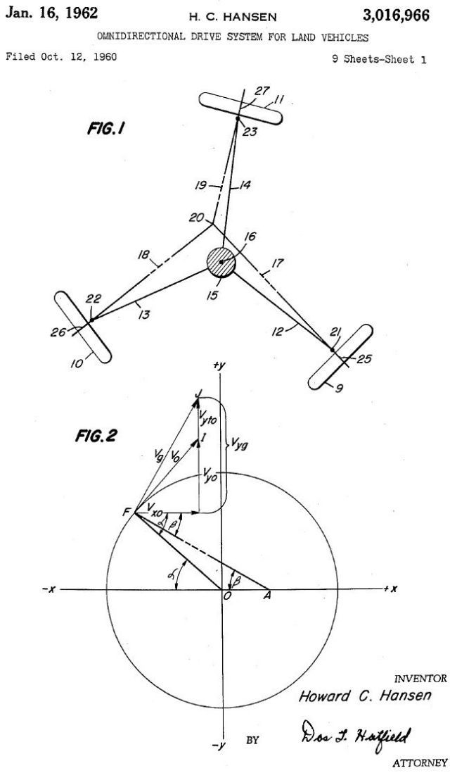
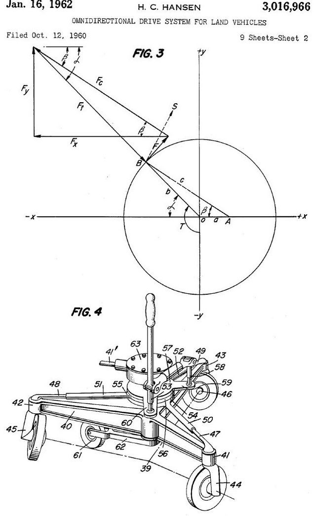
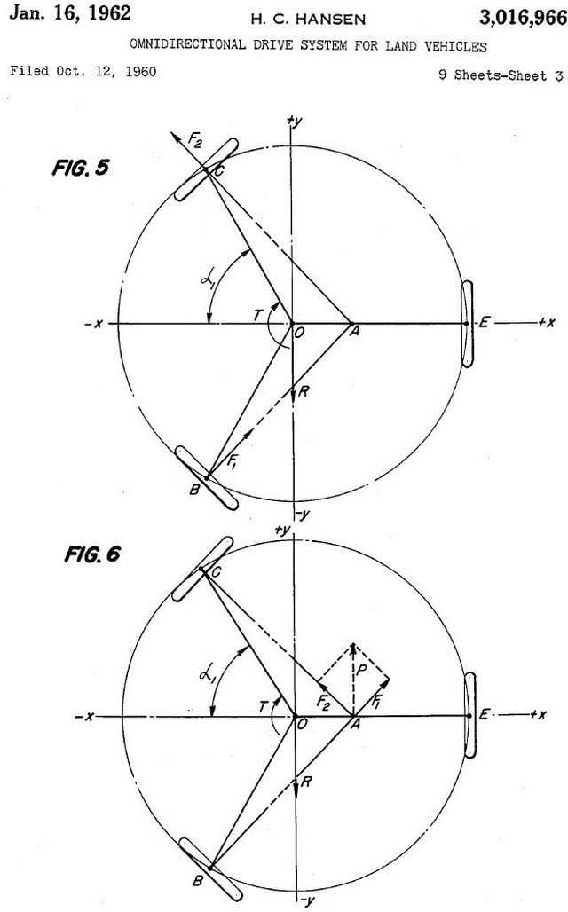
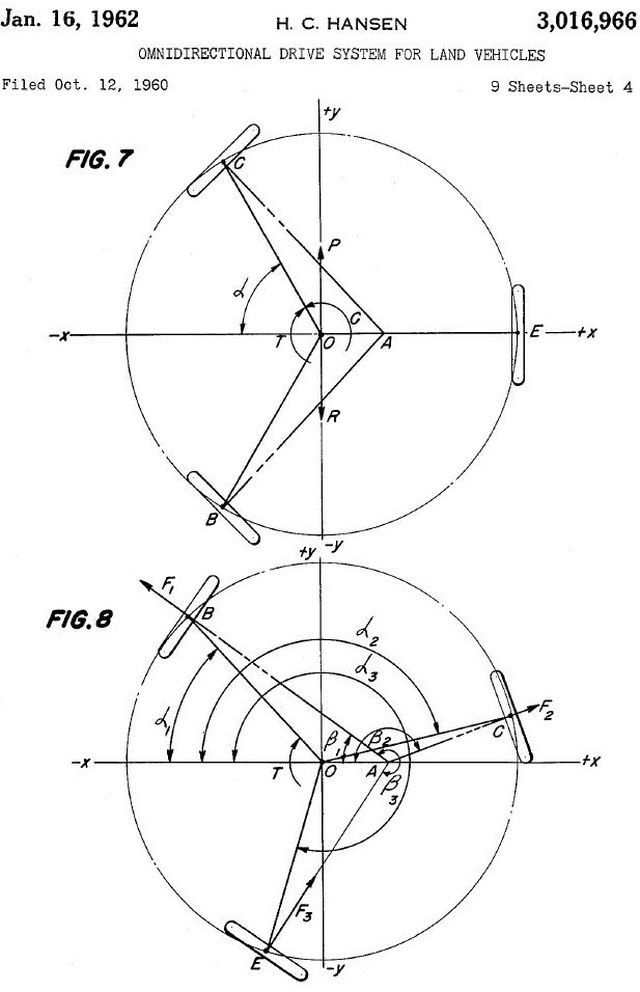
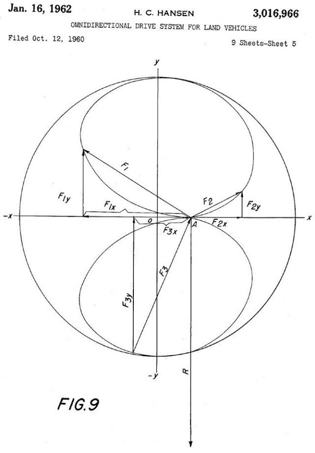
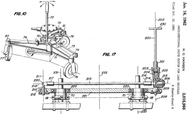
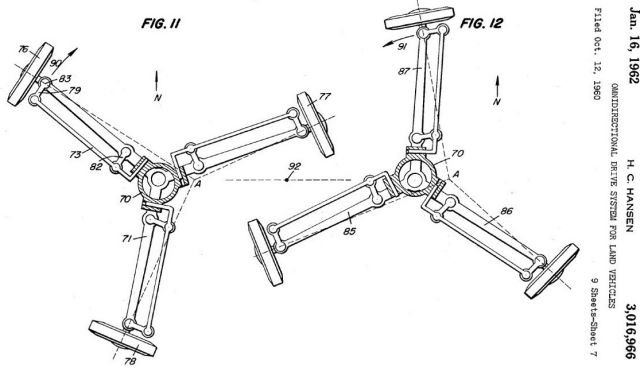
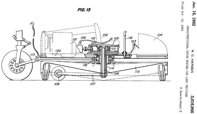
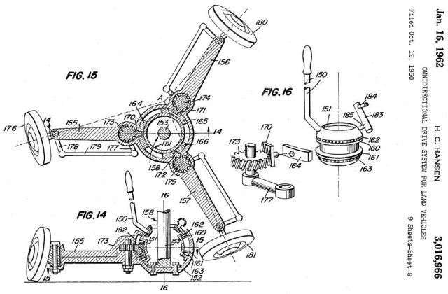
In accordance with the invention, a vehicle main frame supporting the power source, drivers seat and controls 1s itself supported on at least one subframe that is rotatable beneath the main frame. One or more wheels supporting the vehicle are mounted on the periphery of the subframe. The power source may be connected to rotate the subframe and so long as the plane of rotation of each of the subframe wheels is maintained in tangential alignment with the rotation of the subframe, that is, so long as the axes of the wheel axles are radial with respect to the center of rotation of the subframe, the wheels will roll in a circular path on the ground and the subframe and the main frame will not translate in relation to the ground. The subframe wheels rotate on short shafts and are provided with kingpins and steering arms which are connected to a single control lever or column attached to the main frame of the vehicle. The control column is universally mounted and may be tilted in any direction and, so long as the control column bears a prependicular relationship to the plane of rotation of the subframe, the wheels are constrained to roll in a circular path on the ground as described above. When the control column is tilted in any direction away from the above-described perpendicular relationship, suitable linkage connecting the control column to the steering arms of the subframe wheesl causes the rotation of the subframe to vary the steering angles of the subframe Wheels; in sinusoidal fashion, thereby causing the subframe and the main frame to translate with respect to the ground. The interconnecting linkage is such as to cause the period of the sinusoidal variation of the steering angle of each wheel to be equal to the period of one revolution of the subframe, and such as to cause the phase-relationship between the rotation of the subframe and the steering angle variations to be determined by the direction in which the control column is tilted, and such as to cause the magnitude of the steering angle variations to be determined by the degree to which the control column is tilted. The arrangement is such, therefore, that the direction of movement of the vehicle is determined by the direction in which the control column is tilted, while the speed of the vehicle movement and, inversely, the mechanical advantage of the tractive effort are determined by the degree to which the control column is tilted. Thus complete maneuverability and controllability of the land vehicle are obtained with the use of a single control column. One or more trailing wheels may be fixed to the vehicle main frame to establish a heading for the main frame and to prevent contrarotation of the vehicle main frame, or a second subframe may be utilized to provide a means for controlling the heading of the main frame of the vehicle relative to the direction of movement of the vehicle over the ground.
Similar Drives used in Robotics:
Trochoid Drive by Osaka University – See Patent US8757316.
Publication date 24 Jun 2014
Filing date 7 Jun 2011
After reading, I understand quite clear about the self-propelled land vehicles. It is a excellent article. Many thanks