"Sparky" the Robot Pup appeared in Dec 1958-Jan 1959 issues of Popular Electronics. Full pdf here Sparky the Robot Pup PE Dec 1958-Jan 1959.
HOW IT WORKS
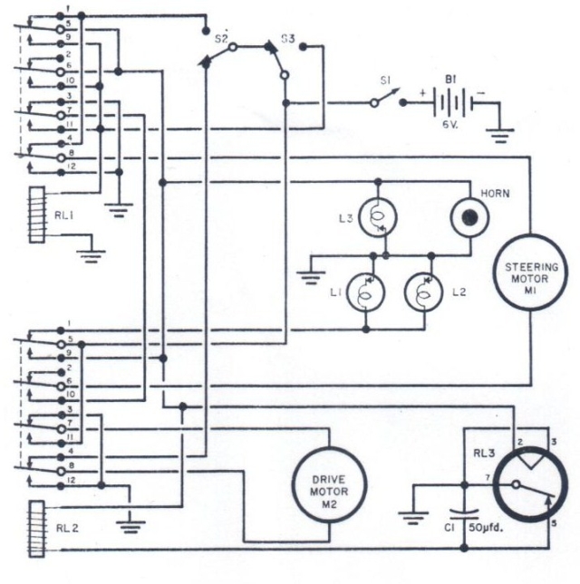
When main switch S1 is closed, all relays stay in their unactivated position and power is supplied only to the drive motor (M2) and "eye" lights. The robot moves forward until one of the feelers contacts something with enough pressure to close switch S2 or S3. When the left feeler closes S2, the following sequence is initiated. RL2 is energized and electrically locks in. Contacts 7 and 8 of RL2 reverse drive motor M2 and energize steering motor M1.
The latter is polarized to turn away from direction of contact as Sparky rolls backward. RL2 also disconnects L1 and L2, turns on L3, and supplies heater current to RL3. The other pole of M1 is supplied from contact 4 of RL1. After three seconds, RL3 opens, releasing RL2, so that the circuit reverts to the normal forward running condition.
When the other feeler arm closes S3, both relays are energized, causing M1 to swing in a direction opposite to that of the S2 closed condition. All of the other reversing operations are similar. Movement of the robot is really a random path determined by the heating time of RL3. If RL3 is warm, turns and backing cycles are of shorter duration.
Mr Welker has an interesting writing style -"…If drive motor polarity is correct, Sparky should take off for the nearest table leg."