Popular Mechanics Nov 2003 (Sth African edition)
Walk tall, break a leg.
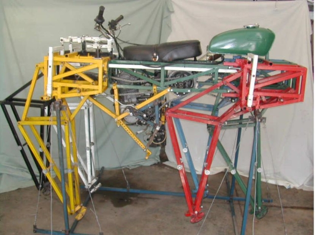
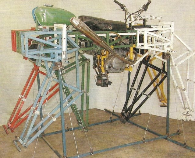 Left: It may not look a thing of beauty, but Boris's Gauteng Walker has been known to go places.
Johannesburg engineer Boris Ingram thought it would be fun to design a walking machine. That was before he got started…
IT'S a fair bet that most of us don't fall asleep thinking about skeletal machines and principles of static determinacy. But Boris Ingram is an engineer in the classic mould: relegating the easy and obvious to their proper place, he concentrates instead on technological challenges.
Take the beast known as "Boris's Gauteng Walker". It's a somewhat complicated assemblage of square-section steel tubing, nuts and bolts, with a disreputable-looking motorcycle plonked on top of it. Being an engineer, Ingram think it's unfair to assess his creation on aesthetic grounds.
"I got the idea from a magazine article about Dutch physicist and artist Theo Jansen, who had built what he called 'Strandbeeste' — large constructions of plastic conduits, with legs and huge sails, that were blown by the wind across the beach. The article described how the leg mechanism was modelled and how the linkage dimensions were optimised on a computer." Intrigued, Ingram began to think about building his own walking machine, using mechanical linkages in place of legs. Trained as a mechanical engineer at the University of Cape Town in the 1970s, he'd taken in some useful stuff on kinematics and linkage types. "It may have been the combination of computers and interesting machines that provided the impetus, or perhaps it was the old joke, 'How do you motivate an engineer?' — 'Tell him it's impossible'. But whatever it was, I decided I needed to write some software of my own."
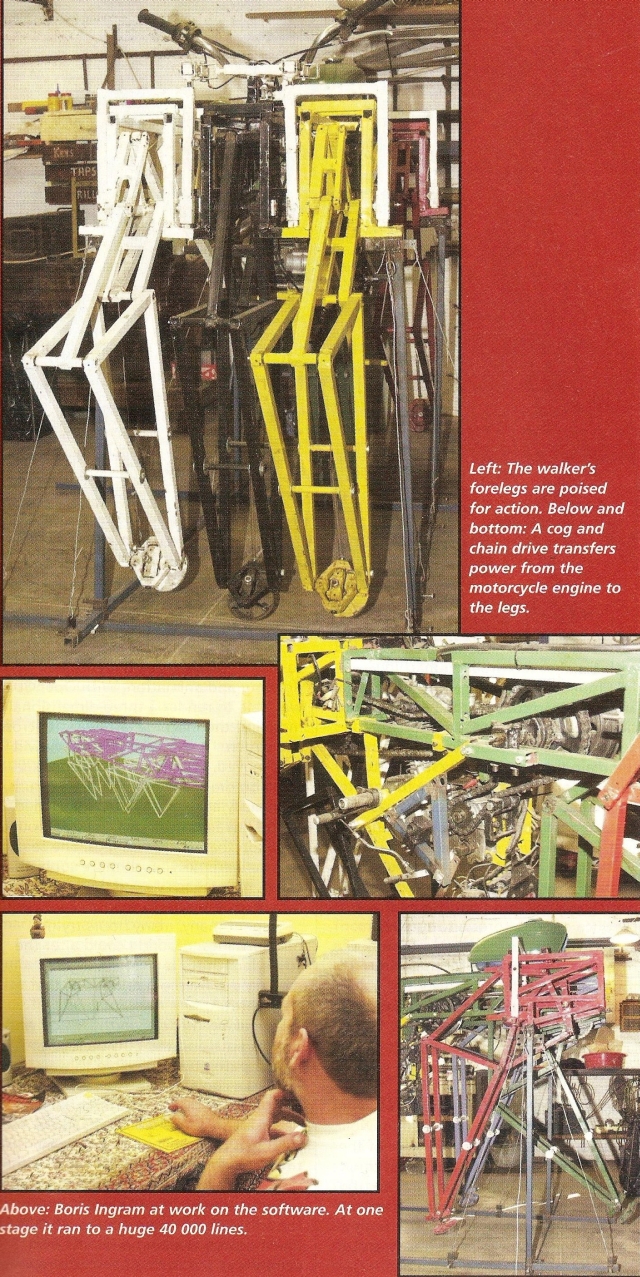 Left: The walker's forelegs are poised for action. Below and bottom: A cog and chain drive transfers power from the motorcycle engine to the legs.
The software
To model the linkage, he started by numbering the links and nodes. Next, he needed to work out the intersection of two circular arcs, the formula for which he found in an old programmable calculator manual from UCT.
"Intersecting circles have two intersection points. The tricky bit was to work out which of the two was the one I needed, for each intersection, for all crank angles. When I had solved this, it was relatively easy to work out the positions of all nodes, knowing the crank radius, the crank's angular position, the fixed pin position and the lengths of the links. This was done for one hundred different positions per crankshaft revolution. I could then calculate the velocities and accelerations of the nodes. I used this data to draw a picture of any linkage for any crank position, and to animate the leg turning."
Unfortunately, as Ingram discovered (and artist Jansen already knew), there was an infinite number of theoretically possible mechanisms.
"He had employed a 'genetic algorithm` — whatever that was. Which was the best one to use for a walking machine? How would I recognise it when I found it? I decided on a brute force approach, to try every imaginable linkage and think of ways of comparing answers.
"Any vehicle has to have three points of support at all times; otherwise it will fall down. This is called 'static determinacy' — you can work out, or determine, all supporting forces in the structure. With fewer points of support, the structure will fall, so you need a stabilising force to prevent this.
"In motorcycles and bicycles, with two points of support, the stabilising force is provided by the gyroscopic action of the wheels, which happens only when the bike moves. Any biker will tell you that you must put your foot down when you stop."
First, Ingram worked out the basics:
"If there was a mechanism that spent 75 per cent of its time with the foot point on the ground and 25 per cent returning to the beginning, then a vehicle would be statically determinate with four legs, as three of them could be on the ground at all times. "This became the main search criterion. Other criteria were a flat walking curve and the longest stride for the shortest total length of links."
The software ran for two days, calculating 16 million different possible mechanisms and scoring them with a weighted score reflecting the criteria. Most could not be solved; "only" 300 000 working leg designs were found.
But no linkages gave 75 per cent ground time, so the walker could not be a quadruped. The software also provided detailed kinematical data, including the work needed to turn the crankshaft against inertia, gravity and the weight of the vehicle.
Recalls Ingram: "This was way beyond anything I had done at varsity, and I'm still not convinced that the mathematical analysis was right! The data showed one intriguing thing — nearly half the time, the work required was negative, suggesting that the mechanism was self-powered for some of the time. This seemed odd, and very counter-intuitive."
Intent on solving the problem, he decided to make a small working model of a single leg. Another long computer run was done, this time with the ground time criterion removed. If the walker had six legs, he discovered, the criterion became irrelevant. In the event, all mechanisms had a walk time of more than 50 per cent.
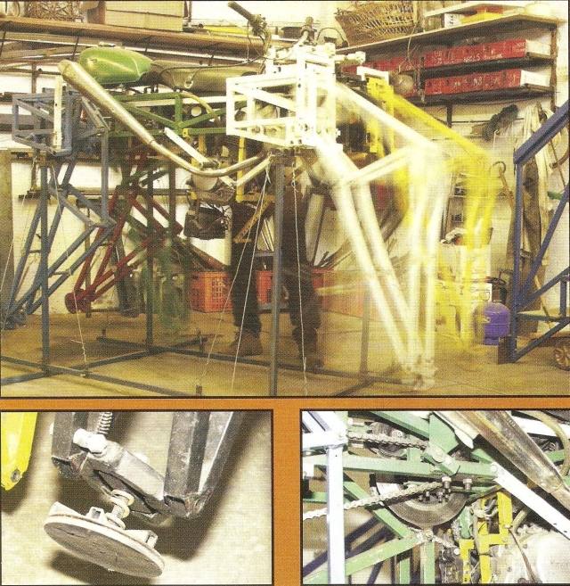 Right: Look ma, no wheels! With the Kawasaki engine turning over nicely, Ingram's walker goes through the appropriate motions. Below left: Each leg was equipped with a spring-mounted-footpad to absorb some of the shock when walking. Below right: Ingram spent many hours refining the leg design.
The paper leg
"I needed a way to make an accurate model quickly and easily, so I printed a development of a cylindrical link and wrapped this around a drinking straw.
The pivots at the ends piece were made from a strip of cardboard rolled into a spiral and stuffed into a short length of straw. This was glued into the end of the link, and the paper folded over to provide tensile strength. The pins were normal household pins, as used in sewing.
"With one leg under my belt, I decided to build a working model, a real walker that could move on its own six legs. I extended my paper and straw technique to make flat panels. It took about a month to finish, but eventually I was left with the first real walking machine.
"I found a gearbox from an old printer and used it to convert the weight of a clock weight into rotary motion. The gearbox was mounted on a pivot above the main tub, driving the crankshafts with a toothed belt, also from the printer.
The pulley for the clock weight was mounted on another tower atop this one.
"Unfortunately, this arrangement did not work, as the crankshaft sprockets were too small and the drive couldn't produce enough torque to turn them.
Later, I thought of using two groups of three legs each, each group moving together and acting as a tripod. I modified my software to handle the new layout.
"It could now draw a side view of the machine, and by drawing the legs in motion, I could make an animation of the new design actually walking across the screen. Encouraged by this, I taught myself how to use OpenGL, the Microsoft extension that allows programmers to 'easily' tackle three-dimensional drawing and animation. With OpenGL I was able to render a three-dimensional model of the machine and walk it across the screen. I could rotate it and view it as it moved, from any orientation.
"I also did many more searching runs, eventually evaluating 120 million theoretical linkages, from which I got around 2 million that worked as legs. The search criteria were now much more sophisticated, rating each design on 15 different aspects of their performance.
"I spent many, many hours trying different legs. I found I could alter the stride length for a given linkage by moving the fixed pin relative to the crankshaft."
By making the legs on the inside walk a short path and the outside legs a longer path, it was possible to walk around a curved path. The reverse of this principle makes a differential gear necessary in a four-wheeled vehicle.
"It was definitely time to take my theoretical models back to reality, if for no other reason than to see if this new steering scheme would work. Besides, the software was now a huge, 40 000-line monster, creaking under its own complexity and in dire need of a rewrite.
"I have a small workshop, the main attraction being my late father's 'Granville Senior' lathe. It was probably quite grand in its day (50 years ago) and has many attachments, but it is definitely showing its age and years of hard use. I also have a small pedestal drill, electric hand drills and two air-cooled arc welders (to give a usable duty cycle)." He bought an electric bandsaw, because there was going to be a lot of cutting. The chosen construction material was 25 mm square steel tubing as it was cheap and he knew how to work with it. Ingram knew that friction would be a problem. He needed to design bearings that would be efficient, yet cheap and easy to make. He came up with a design made from piping for shafts and their housings, as he didn't think the old lathe was up to machining every pivot.
"I had polyacetate bushes made, with suitable thrust washers. There is a small size for the linkage pivots and a larger one for the crankshaft and transfer shaft main bearings. Solving the bearing problem was pivotal in convincing me of the practicability of building a real walking machine, strong enough to carry me."
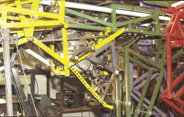 Left: Three steps forward, three steps back. Ingram's walker project was by no means plain sailing.
The steel prototype
With the boilermaker's motto ("We're not building watches here") firmly in mind, Ingram started with the structures that hold the crankshafts and the leg pivots.
"I don't know how many holes I drilled, threads I tapped or pipes I bored. I broke many, many tools, especially M6 hand taps — I think five sets, and a similar number of 2 mm drill bits. Though I tried to keep machining to a minimum, due to the dodgy lathe, there was still a lot of it — several hundred pieces. There was also a lot of welding, grinding and filing. By the end I was literally exhausted!
But the finished product seemed worth it."
A 200 cm3 Kawasaki motorcycle provided the engine, electrical system, fuel tank, seat and a host of other bits. This engine was chosen because it was the smallest he could think of with an electric starter; he didn't want to kick the "horse" over while trying to start it.
"When demonstrating the machine, people are always amazed that I can just walk up to it, turn the key, press the starter button, and it bursts into life!"
"The idea of feet was to prevent the tripping fate of the paper walker. The foot was a universal joint, with a spring-mounted central footpad. The rest of the leg had no vertical flexibility. When walking, the legs would need some vertical 'give' to reduce shock loads as weight was transferred from one set of legs to the other."
The machine stood on its own custombuilt stand, designed to allow the legs to move. It was run extensively in this stand, allowing minor problems to be fixed.
"Eventually it all worked fine in the stand. The legs moved quite quickly — the gear ratio was too high. Also, the load on the engine varied a lot, judging by the change in engine note as it ran. It certainly worked hard, especially when starting, as the whole machine is lifted in the first part of the walking action.
"Although I believe I could have gunned the engine enough to make it walk, it felt like it would have made off at a pace, and I was concerned that if the feet jammed, the whole contraption would come crashing down. Carried 1,5 m off the ground, the rider would be flung far and land hard. I had fallen off enough motorcycles to want to avoid this."
Final testing meant walking across the workshop floor — about three paces of the machine. It couldn't turn in such a short space; so, after every test walk, it needed to be walked in reverse and lifted back on to the stand to fix the latest glitch.
Recalls Ingram: "I did so much lifting, walking three steps, going backwards three steps, then lifting again, that I decided I needed a small trolley to move it around the workshop. The irony of building a car to carry a walker was too much!
"The grease also got to me. All the lubricated joints leaked and soon the thing was covered in gunge. Tinkering became a messy business." It freaked out the clean, clinical programmer in him. The last straw came during the test of the latest coupling fitted to the front crankshaft.
"It sort of worked, but seemed to become floppy after repeated loading. While reversing back to the stand, the blue leg on the rear crankshaft jammed its foot and broke its coupling. I managed to hobble the walker back on to the stand, but it was not sitting properly."
Then, while he was checking the blue leg's problem, the red leg's coupling also broke as the leg jammed against the stand. With a very broken walker and a tired and discouraged developer in a quandary of mutually conflicting design requirements, it was time to call a halt.
"The problems have been challenging, and I have managed to solve only a few of them. Perhaps, with a good cleaning and a few minor repairs, it'll be time to start walking again…"
Doc thesis
A.J. Ingram, A new type of mechanical walking machine, University of Johannesburg, 2006
Masters dissertation
A.J. Ingram, Numerical kinematic and kinetic analysis of a new class of twelve bar linkage for walking machines, Rand Afrikaaans University, 2004
For the masters, the document to download is "numerical.pdf"
Hi Boris, just googled your amazing invention. How are you keeping? xxxxxxxxxxxxxxxxxxS