Although published in 1962, the illustration is dated 1961. Frank Tinsley's concept pre-dates A. J. Morrison's "Iron Mule Train" by about 7 years. Given the cancelled Space programme for an un-manned lunar misssion, I wouldn't be surprised that Tinsley's concept inspired Morrison in resurrecting the Moonwalker project (having already had a second life as a Disability walker) . In turn, the idea was looked at again in 1990 by D.J. Todd. Currently, the idea is seen in the "Big Dog" project by Boston Dynamics. Some old ideas never die – they just wait to be re-discovered.
ll
Mechanix Illustrated – April 1962
COMBAT VEHICLE “WALKS” LIKE A MAN
An Original MI Design by FRANK TINSLEY
IMAGINE, if you can, machines that walk -”articulated mechanical “mule trains” that could thread a tortuous path through boulder fields and forests and negotiate mountain passes with heavy loads of freight. Sound crazy? Well, our Armed Forces and Space Authority are dead serious about it. Right now engineers are perfecting pilot models that are already walking around laboratories and testing grounds.
One of these devices is the solar-powered Moon Rover vehicle intended for remote-controlled reconnoitering of the moon. Designed by the engineers of Space-General Corporation, the Moon Rover will be lofted to our lunar satellite by an Atlas-Centaur rocket. Upon landing, the six-legged explorer will unfold, raise its panel of sun batteries and, with the power thus generated, march off about its business at a brisk three mph, picking up geological samples with pincer-like fingers, analyzing them and flashing the information back to earth.
The six cam-driven legs of Space-General’s moon scout are arranged in pairs of two sets in the rear and one in front and function so that half of their number are always planted firmly on the ground. A small steering motor turns the vehicle by swinging the front legs in the direction ordered. The joints of the Rover’s insect-like limbs and all the machine’s connecting points are self-lubricating and enclosed in hermetically sealed bellows.
An interim device, the Rover is intended to serve as a midget forerunner of later, manned vehicles. Our primary interest in Space-General’s gadget lies in its use of legs for propulsion, instead of wheels, runners or the like.
An even more ambitious walking machine has been conceived by a Professor of Engineering at the University of Michigan, Joseph E. Shigley. His Army Walker has 16 legs and is designed to walk at ten mph with a man inside it. With the machine still at the experimental level of development, the professor feels that his principal task is to increase its walking efficiency by recovering and reusing some of the power now lost in leg lifting. To effect this he is studying the power-storing possibilities of the flywheel and the hydraulic accumulator. His present thinking envisions a vehicle supported by expandable legs which are mounted in groups of four at either end of two fore-and-aft axles. At any given moment four of these legs -”one in each group” -will be planted on the ground; another four will be lifting for a new step; four others will be fully raised; and the final four will be descending.
MI’s own version of a mechanical mule train is shown in the accompanying illustrations. Though rather more complicated than current designs, it is, we think, better adapted to rough terrain than either the Moon Rover or the Army Walker.
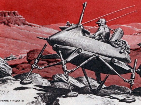
The MI Walker is an amphibious cargo and personnel carrier. Extending from the vertically orbiting “thigh” of each unit is a telescopic lower leg equipped with a depth-sensing electric eye and a pressure-activated clutch. When the Walker takes a forward step the electric eye calculates the distance to the next foothold, then automatically extends the lower leg to the required length. Once its inflated pad-like foot has been solidly placed, the machine forges ahead. As its advancing weight shifts to the outstretched leg the pressure clutch tightens automatically. The leg sequence is so phased that three of the control unit’s four feet are always on the ground and form a balanced tripod base. Thus, taking long or short strides as the terrain dictates, reaching down to low-lying footholds among the boulders or up high banks, MI’s Walker picks its way across the ruggedest topography with the surefootedness of a mountain goat.
The Walker’s long, segmented body resembles that of a caterpillar. Its “head” consists of a four-legged command unit which leads the train. However, this can also be uncoupled to function as a free-walking combat unit.
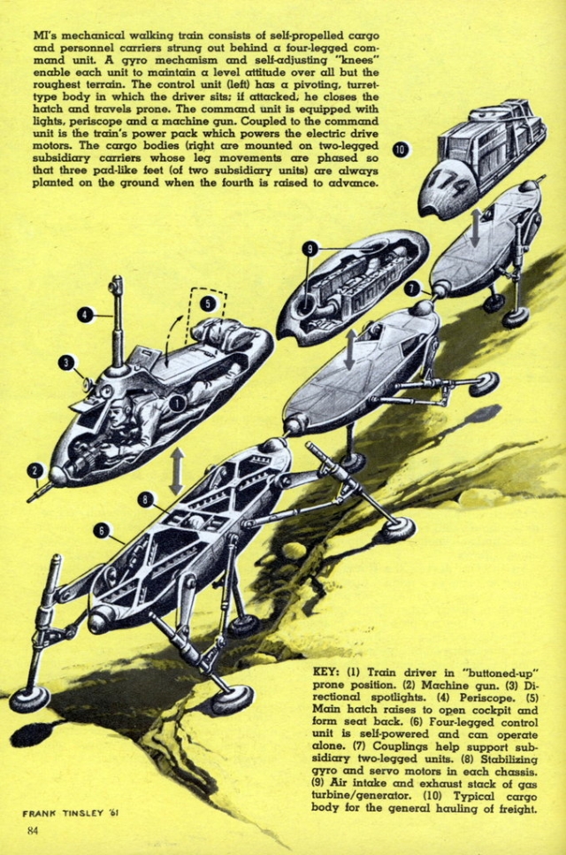
Atop the Walker’s hull is a tank-type turret where the driver sits, safety-belted into an open cockpit whose raised lid forms the seat back. Before him are his control grips, instrument panel, radio set and a telescoping periscope for vision over obstacles. A pair of headlights which can be individually aimed illuminate his path at night and pick out the route ahead.
In event of an enemy ambush the driver slides into a prone position, slams shut the turret hatch behind him and either shoots his way through the roadblock or takes evasive action. His rotating turret-mounted machine gun makes him a formidable antagonist. Short of a direct hit by an antitank missile, he is reasonably secure.
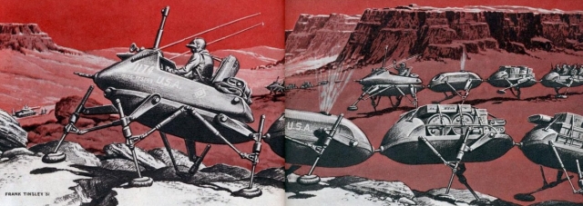
Coupled behind the command unit is the power pack. Equipped with a midget gas turbine /generator and storage batteries, this self-contained powerhouse cooks up the electrical energy that runs the train. Its power is transmitted back through hollow coupling links to all subsidiary units, and fuel carried in each unit’s reserve tank is piped to the power pack by the same route. As shown in the drawings these couplings are ball-mounted to permit maximum flexibility of movement.
Distributing the triangles of support over adjacent units permits the use of two instead of four legs for the subsidiary hulls. As in the four-legged command unit, three of the four feet of two subsidiary units are always planted as the fourth advances.
The hulls controlled by the command unit are standardized. Nested in the rear of each is a gyro mechanism to help keep it on an even keel. Forward of the gyro is a set of drive pumps that power the hydraulic cylinders which operate the legs. All hulls are watertight and designed with sufficient flotation to permit ordinary river crossings. During such passages, the wide-soled feet are alternately feathered and cocked broadside to serve as paddles.
The MI Walker is a notch or two above the rudimentary walkers now under development. However, our version is but another step in a continuing process. More rugged mechanisms and more sophisticated electronic systems are bound to emerge as experiments in the field bring more and more advances. One thing, though, is certain. Eventually man will indeed create a new form of transportation – a truly efficient Walking Machine.
See Mechanix Illustrated Apr 62 pdf here.
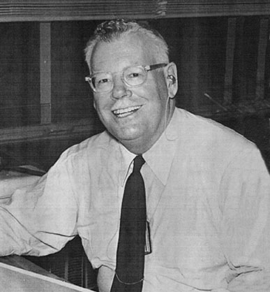
Frank Tinsley was born in 1899. He was a famous American pulp writer and illustrator, and wrote for Mechanix Illustrated in the early 1950's through to the 1960's. He died of a heart attack at his home at age 65 on June 23, 1965.